ESPHome on the Yeelight Monitor Light Bar Pro
Yeelight Light Bar Pro (YLTD003) Teardown
Monitor-top light bars are wonderful for reducing eye strain and fatigue and the effect is even better with a bias light behind the monitor. Enter the Yeelight Light Bar Pro (YLTD003).
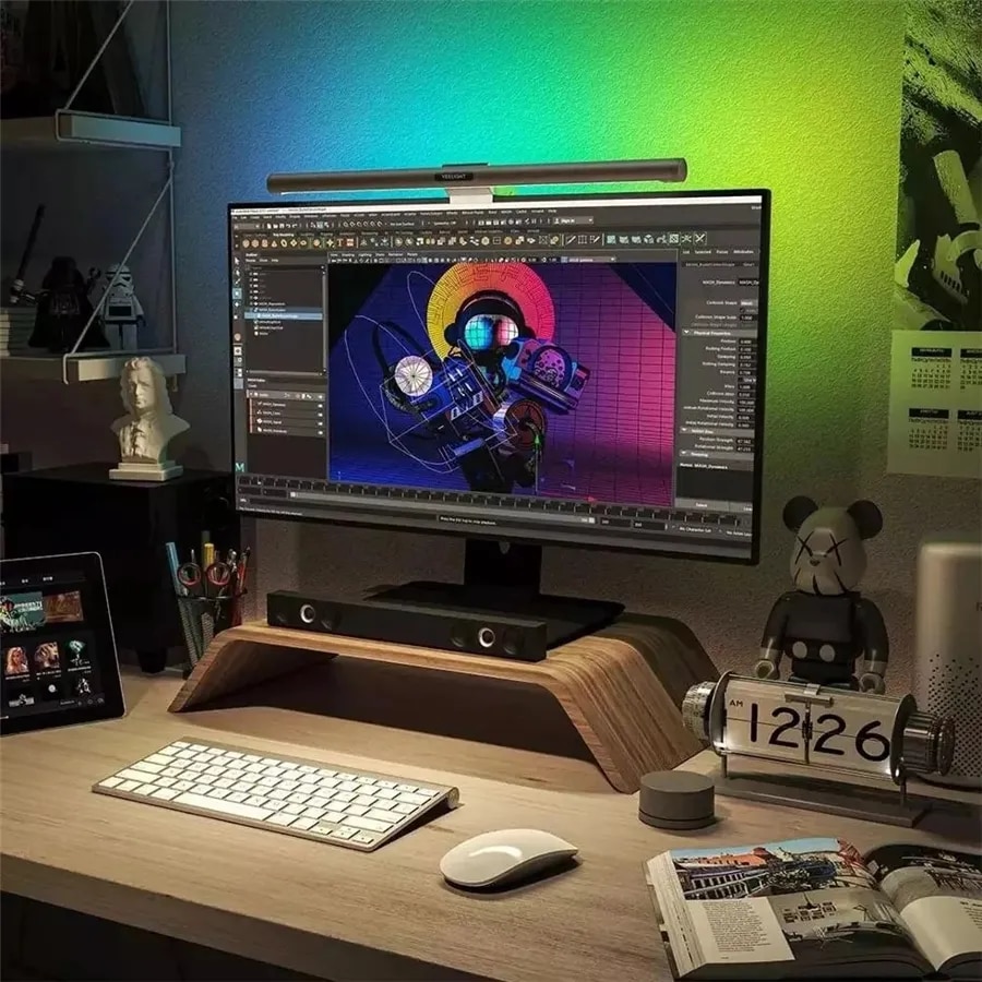
YeeLight marketing photo from AliExpress listing. The background wash light really does help reduce eye strain and fatigue.
It appears to be a pretty straightforward clone of the Xaomi MJGJD02YL that I’ve torn down previously but with some welcome changes internally.
Unbox
Before teardown, quick look at the box. The shipping damage is just part of the Ali Express experience!
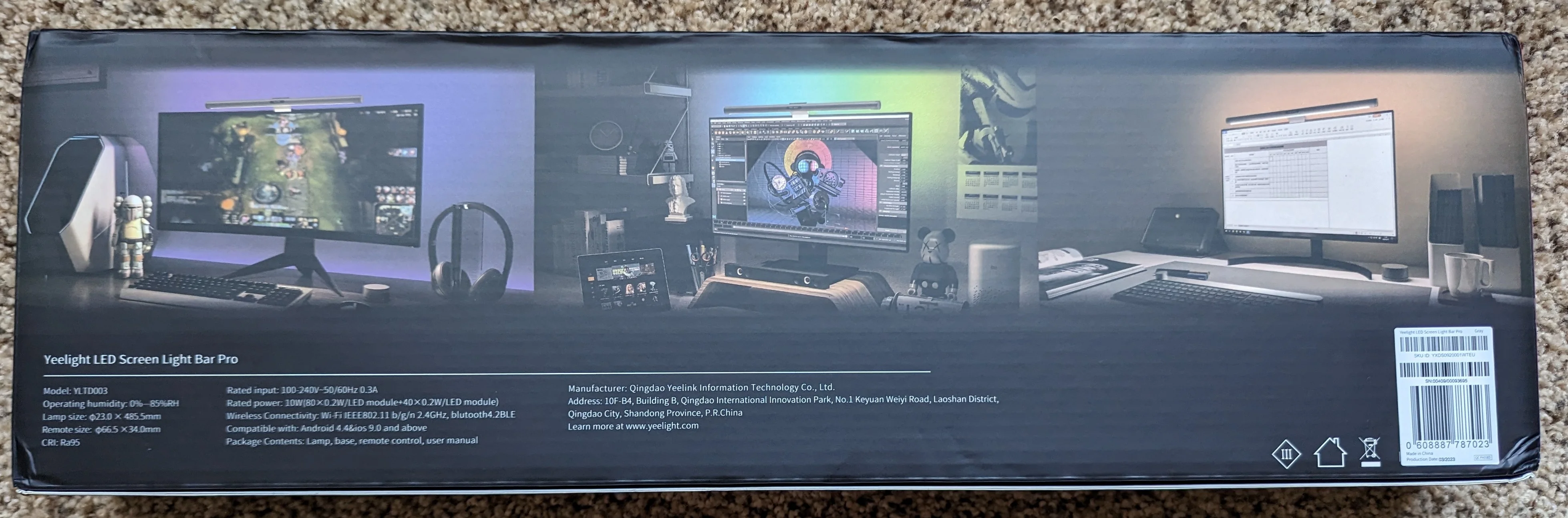
The box isn't anything to write home about. Neatly packed, for what it's worth.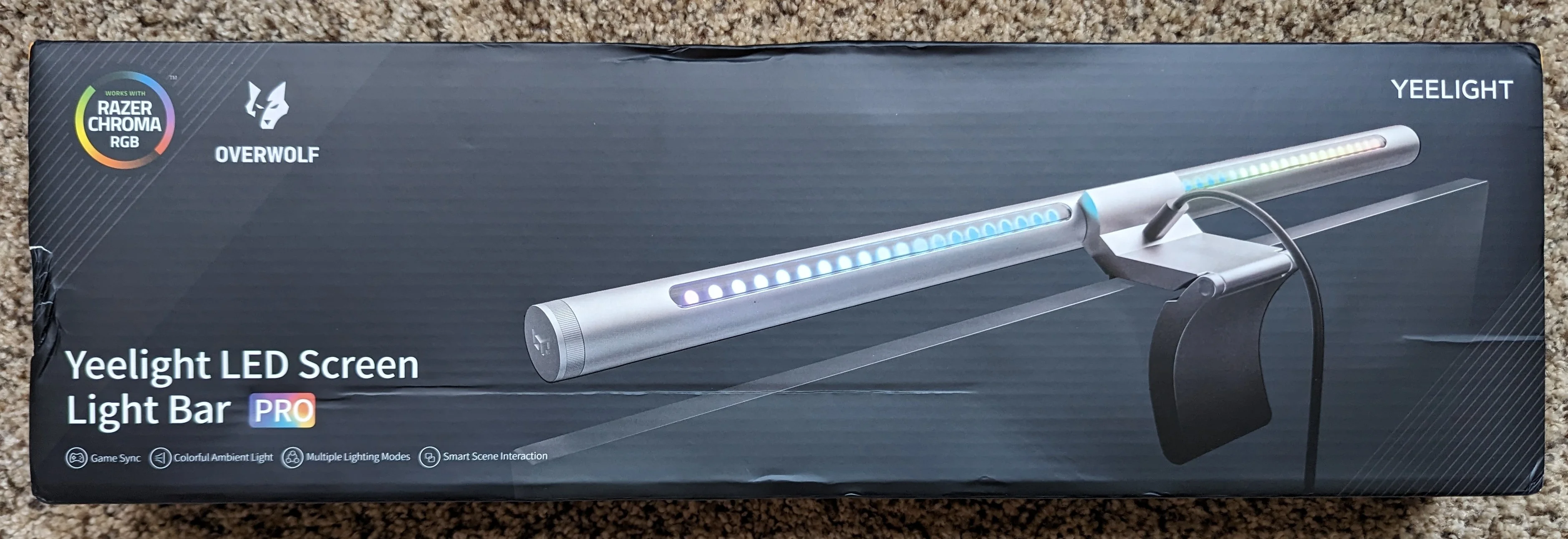

Not only does it look a lot like the Xaomi lamp, it’s dimensionally similar, too. It’s 100% compatible with the mounting bracket that Xaomi shipped with their lamp.
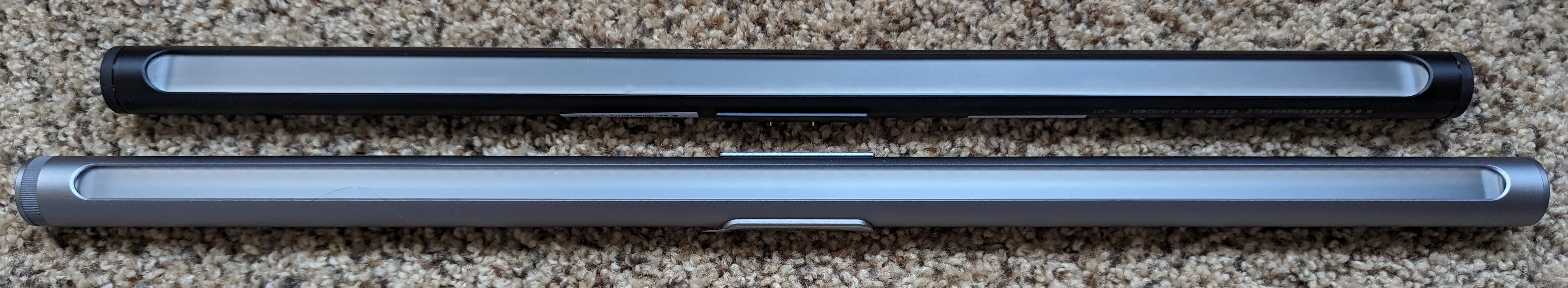
Xaomi desk lamp on top, Yeelight on bottom.
Teardown
I am going to run through a complete teardown.
You do not need to completely disassemble the lamp to replace the ESP8266 with an ESP32.
To access the ESP8266 based module controlling the lamp, you really only need to remove the larger of the two end caps. From there, you will have a few inches of ribbon cable to work with. If you’re careful, you can replace the ESP8266 with an ESP32 without removing the main PCB from the tube but you may find that taking the main PCB out of the tube makes it easier to work with.
Just like with the Xaomi lamp, you will start by removing the sticker covering the small metal protrusion that holds the pogo pins and mates with the power supply “dock”. The pogo pins are one of the two features that keep the main PCB from sliding out of the tube.
Discard the sicker and put the metal piece and the pogo pin assembly somewhere safe. This step is not pictured.
Next, note that Yeelight bar has a larger plastic cap on the left relative to the one on the right. Not only does this cap have a grip feature moulded in, it’s also secured to the tube with a lot less glue than the Xaomi lamp; just grip and twist to remove this cap.
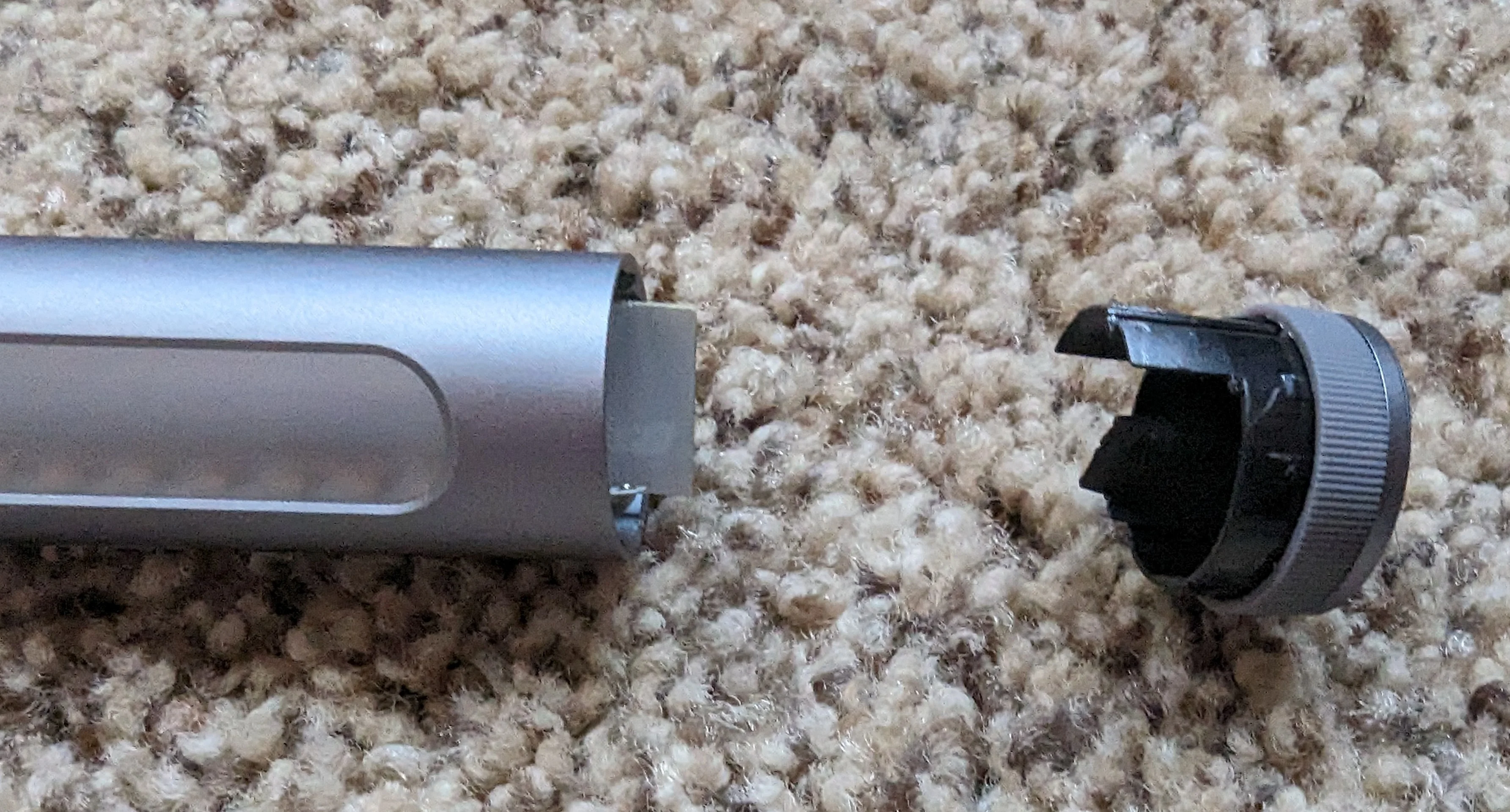
The cap is trivial to remove.
After the end cap is removed, you will be able to see inside the tube. There’s not much room, but the micro controller is on it’s own little PCB attached to the main PCB with ~50mm of ribbon cable. If you’re careful, this is all the disassembly you need to do to access the ESP8266 module.
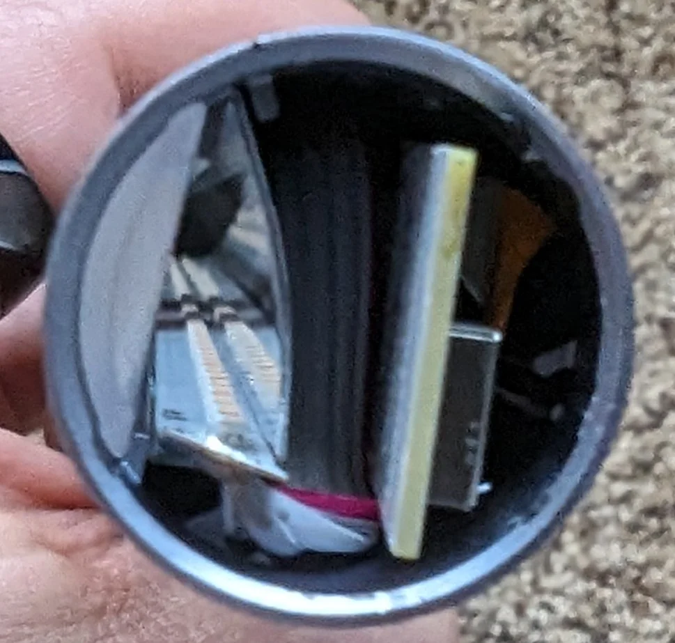
There's not much room to work with. Left most is the cw/ww led strip and reflector. Middle is ribbon cable connecting leds to main pcb. Right most is the ESP8266 module.
As of writing, I could not find any information about which pins on the module are used for programming. I was under a bit of time pressure and wanted to use a more “future proof” ESP32 module anyways so I didn’t bother trying to program the ESP8266 module.
I opted to replace it with an ESP32 module that I had on hand.
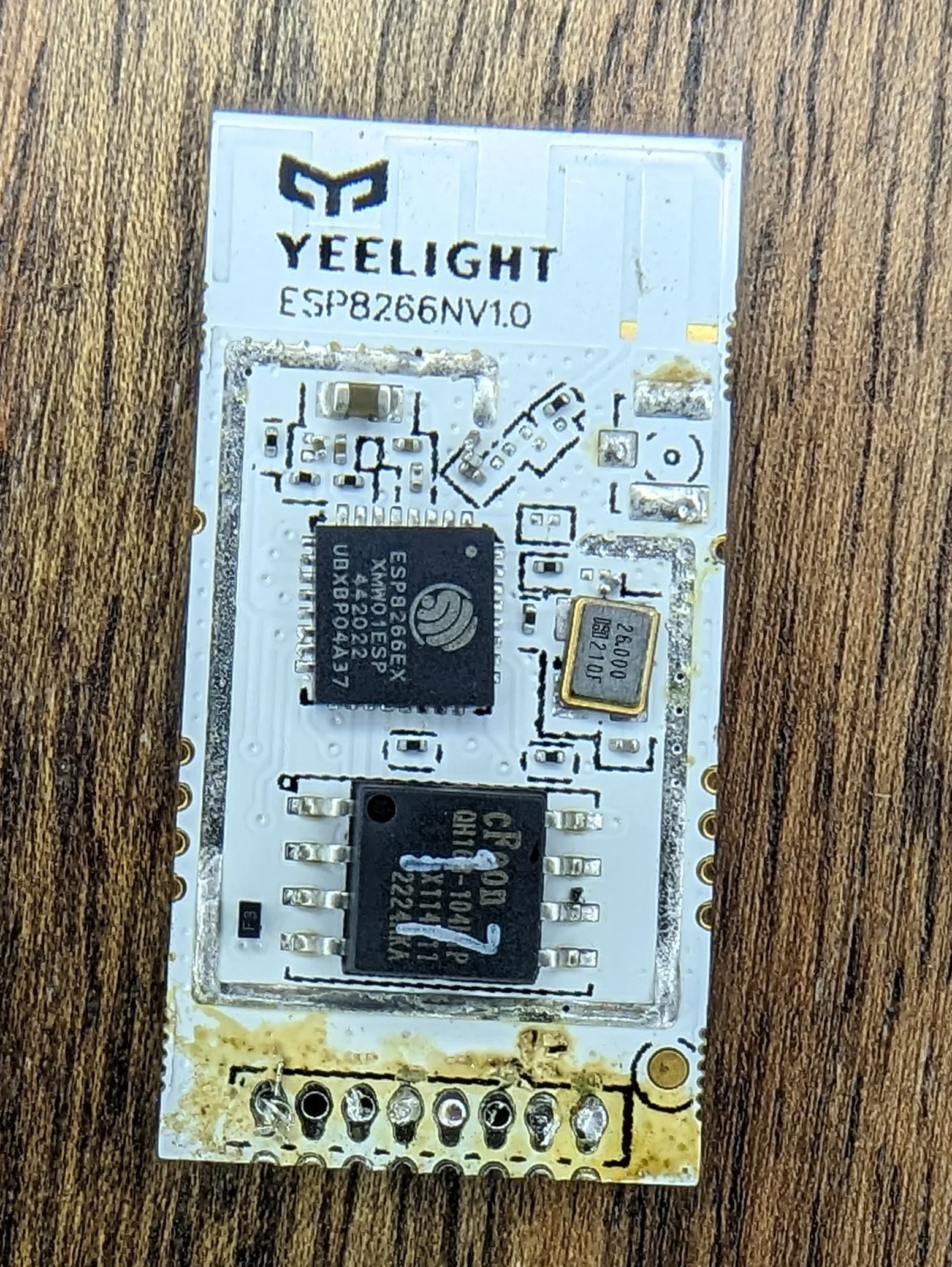
It's clearly an ESP8266 module but the pinout/form-factor are unusual.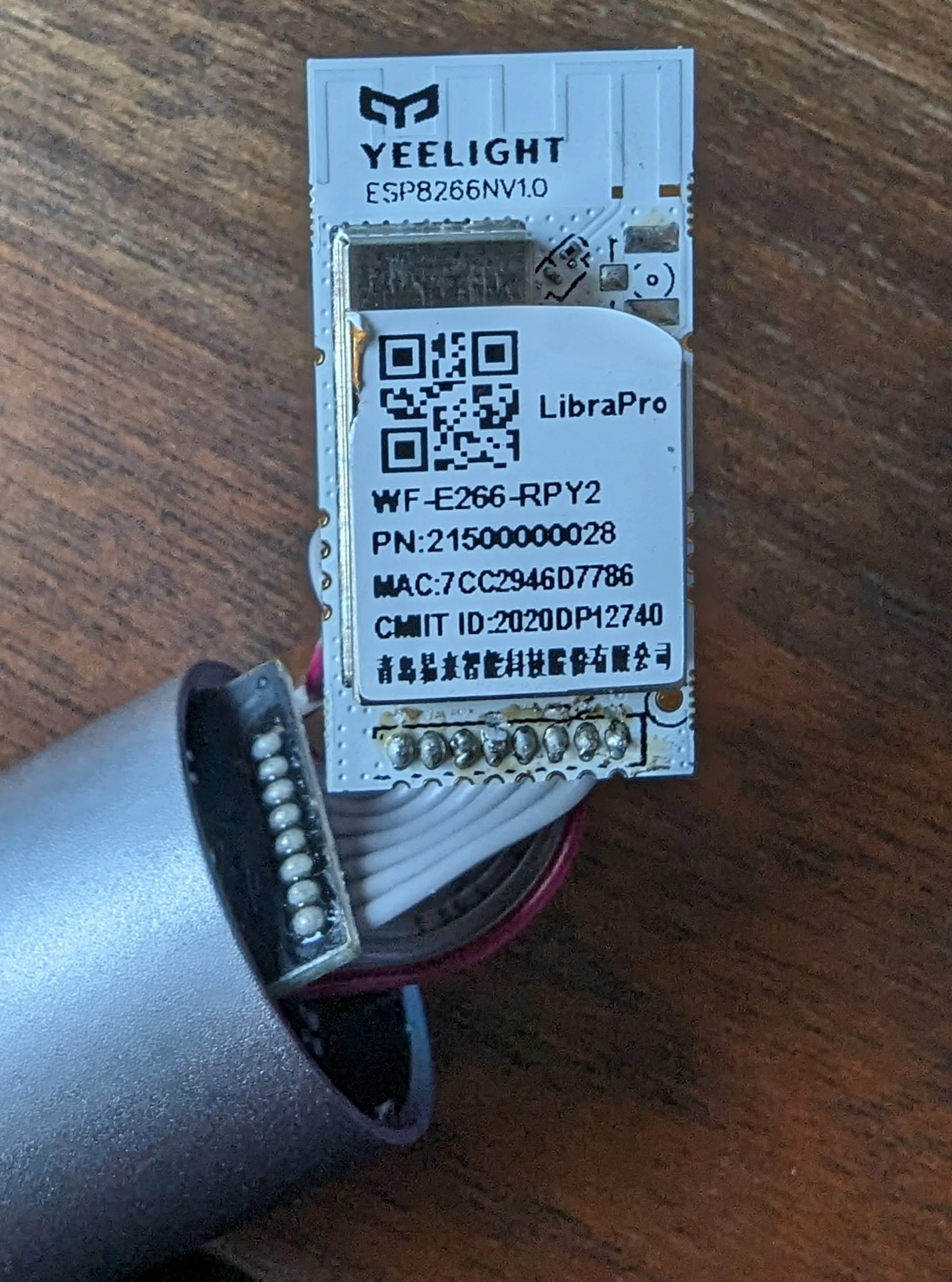
If you want to extract the main PCB from the tube, you will notice that there’s still something holding it in place. That something is the plastic lens closest to the now removed end cap.
Using a small flat pry tool or razor blade, you can carefully pry the lens out of the tube.

Note the plastic lense that used to cover the RGB LEDs.
With the plastic lense out of the way, the main PCB and the cw/ww light ribbon and reflector can be slid out of the tube.
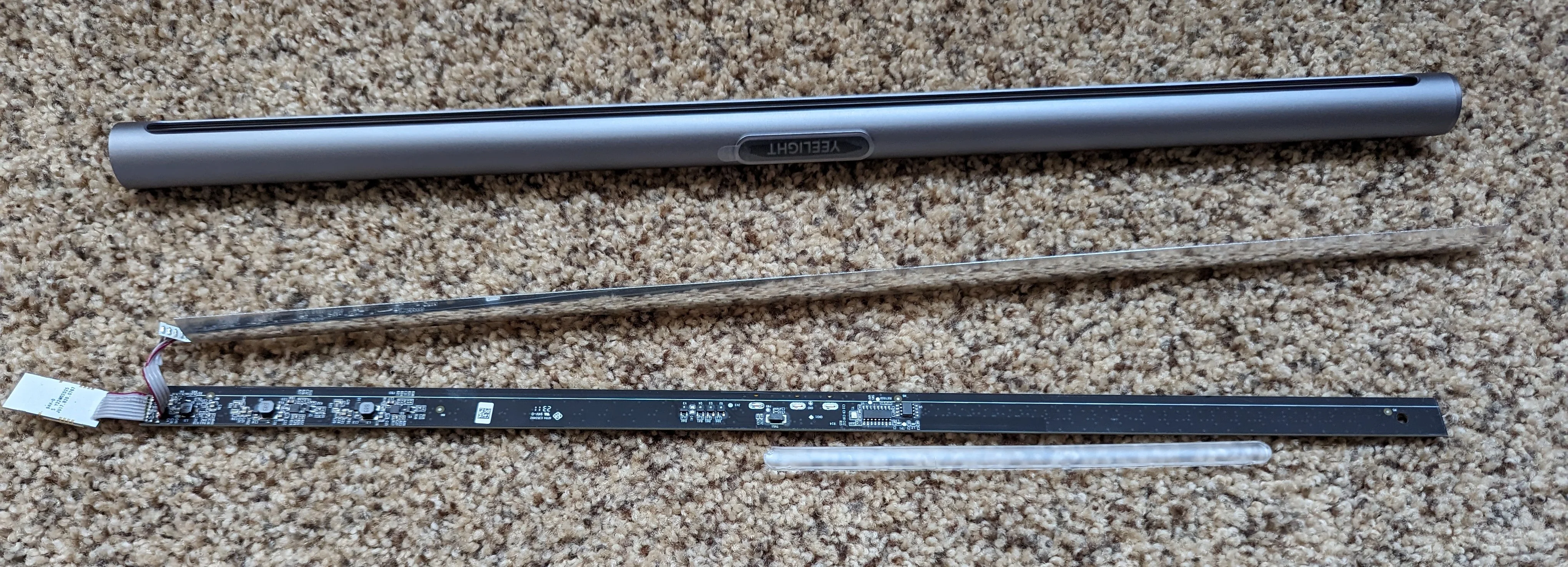
There's not much to it, really. Tube, big PCB and small ESP8266 module on a ribbon cable.
That’s really all there is to opening up the lamp.
Below a few more photos of the internals.

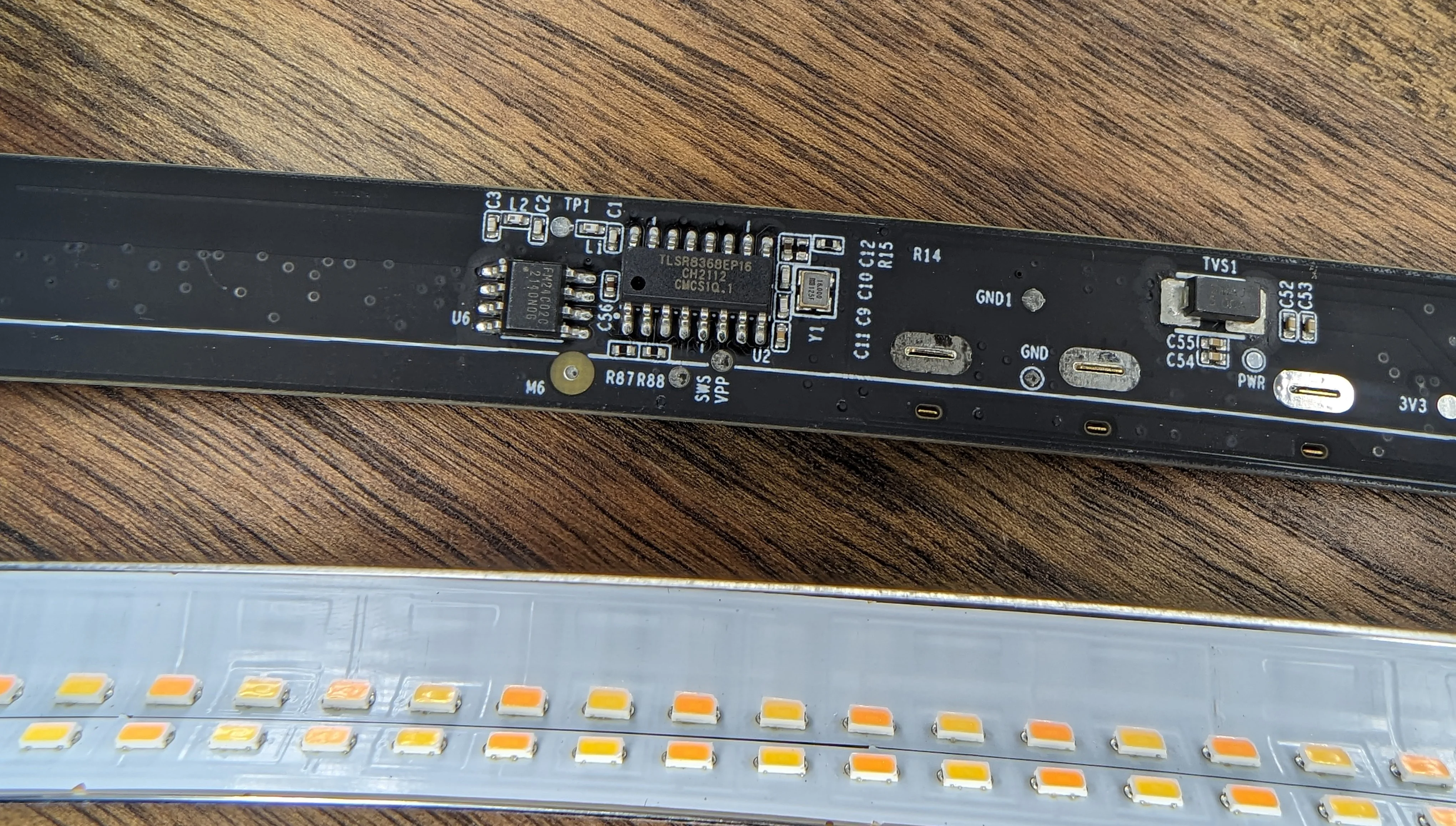
A look at the power regulation and LED drive circuitry.
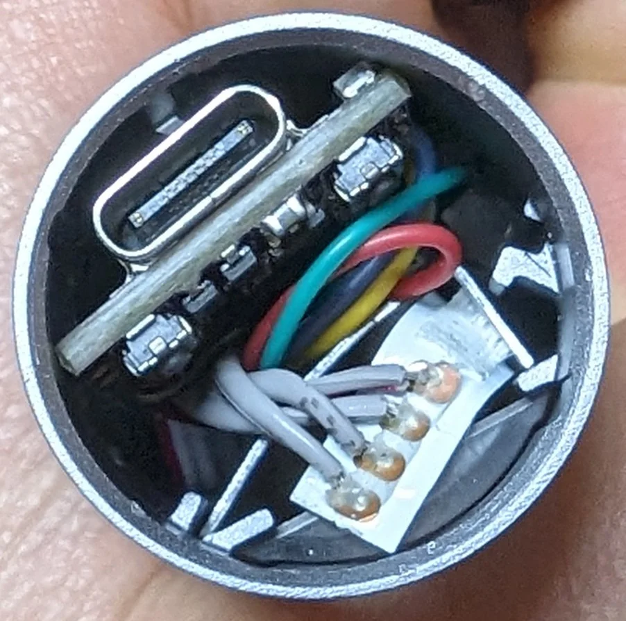
A closer look at the chips for the remote control puck.
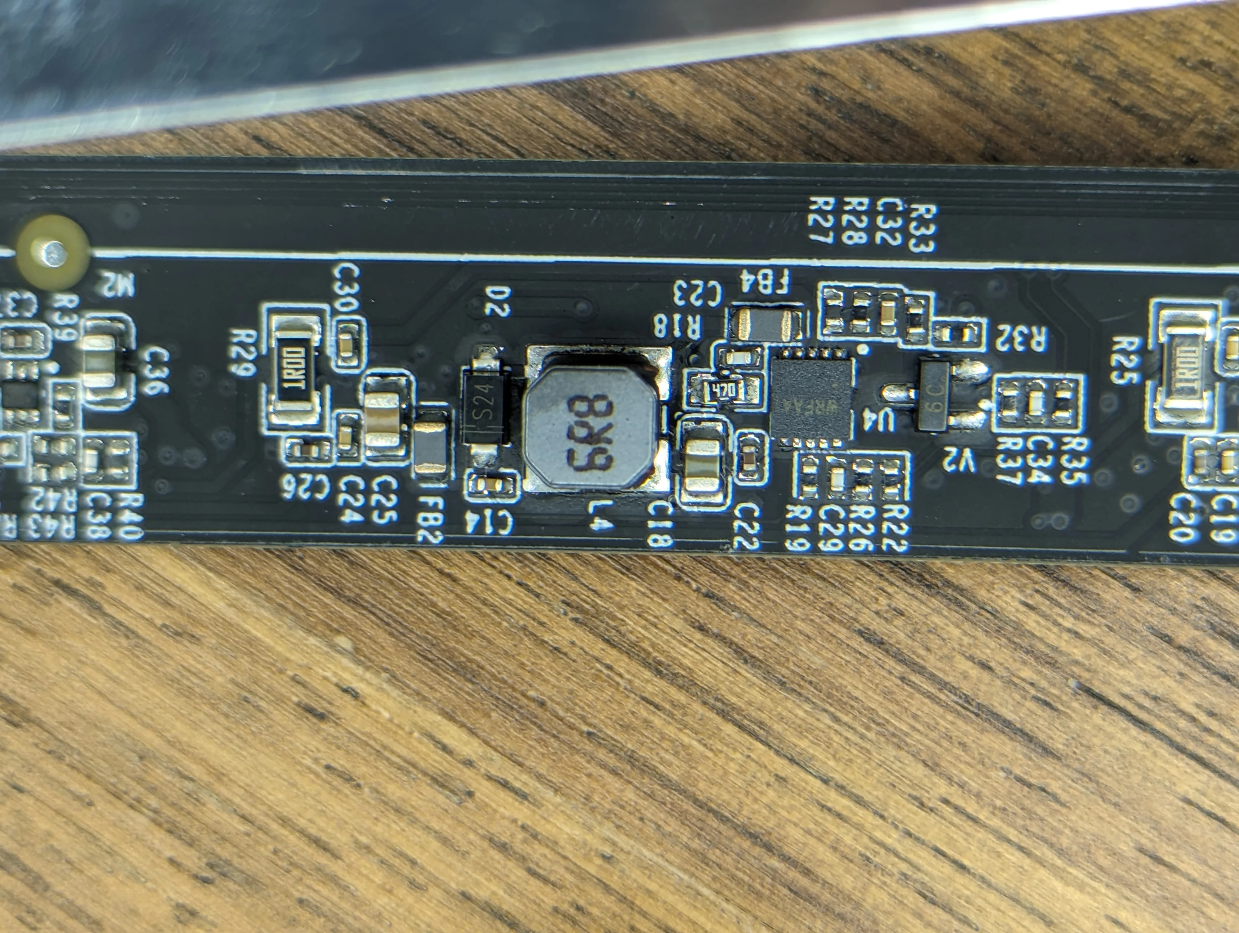
A closer look at the power regulation circuitry.
This is what happens when you are impatient and set the hotplate to an aggressive temperature.
ESP32 Retrofit
Fortunately, each wire connecting the ESP8266 module to the main PCB is clearly labeled.
| Pin | Label | Description |
|---|---|---|
| 1 | GND | Ground for the ESP module |
| 2 | 3v3 | Power for the ESP module |
| 3 | SCL | I2C. (probably, see note below) |
| 4 | SDA | I2C. (probably, see note below) |
| 5 | RGB | Standard neopixel data bus |
| 6 | C | PWM signal for cold white channel |
| 7 | EN | Master enable/disable for all light output |
| 8 | W | PWM signal for warm white channel |
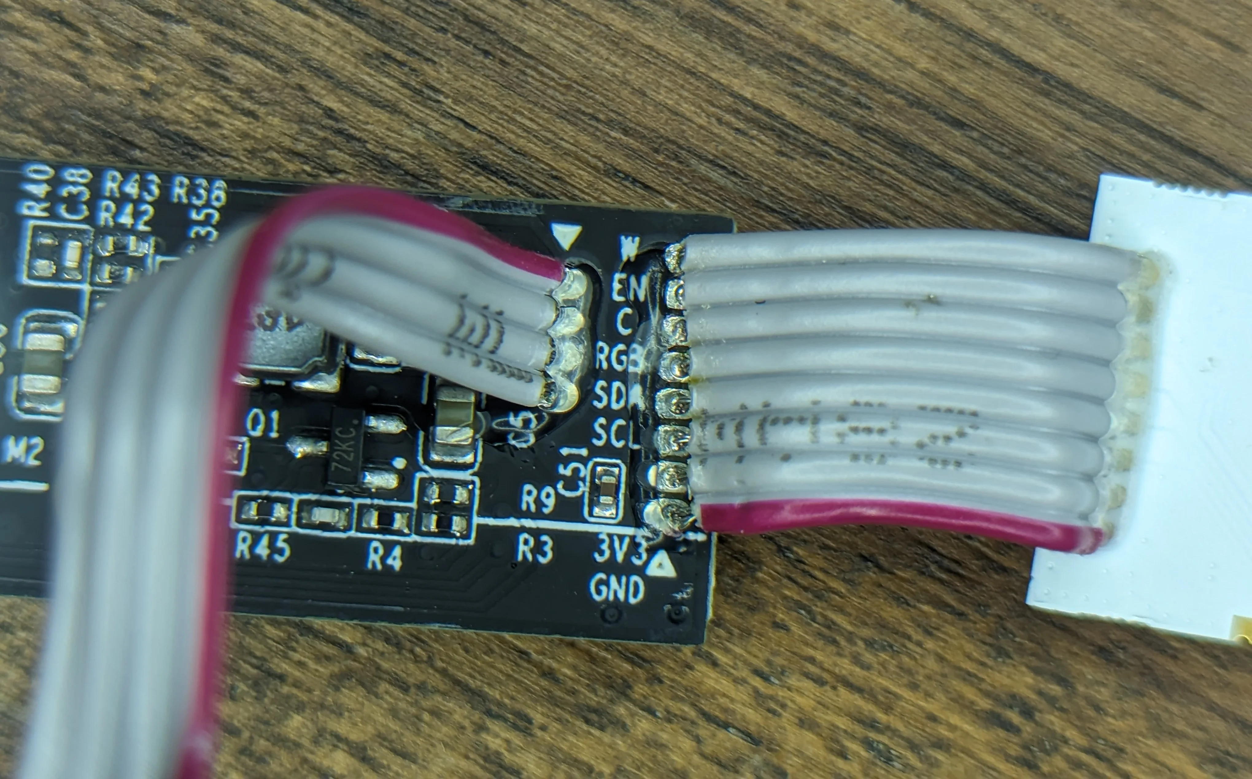
I am eternally grateful for every PCB designer that bothers with clear silkscreen labels.
To drive the LEDs, we only need 4 GPIOs. Two for PWM channels and another two for master output enable and neopixels.
This makes it trivial to replace the ESP8266 based module with an ESP32. The only catch is that the ESP32 module has to be narrow (if you want to fit it inside the tube). If you don’t care about that, you can use any ESP32 module you have on hand but you’ll need to design/make a new enclosure for it.
I had a few of the incredibly tiny ESP32-C3-0.42LCD modules on hand, so I used one and it barely fit:
Tube is quite narrow and the ESP32 module takes up almost all of the available space.
All in all, you want to make sure the module is no more than ~20mm wide and probably not much longer than that either. To make my life easier in the future, I soldered the ESP32 module to the main PCB with AWS30 wires about ~100mm long. You can see the colored wires in the photo above.
I was barely able to fit everything back into the tube. You should probably use wires a bit shorter if you can.
In any case, the extra bulk from the wires and the ESP32 module meant that the OEM end cap would not fit back on the tube without some modifications.
Rather than play a game of “cut some more plastic away and see if it fits yet”, I decided to just model a new end cap in Fusion 360. This replacement cap specifically does not have any features that extend deep into the tube so there’s no risk of it interfering with the ESP32 module.
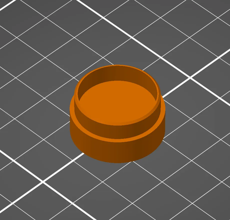
Suggested print orientation. Choose resolution, material and color to suit your needs.
You can download endcap.step file here.
Print it in whatever material and color you want but be mindful of dimensional accuracy; the end cap is meant to be press-fit into the tube.
If you’re confident that you’ll never need to access the ESP32 module again, glue the end cap in place.
ESPHome
Here’s a simple ESPHome config for the device.
esphome:
  # Will boot loop w/o this when using the ESP-IDF and the C3
  platformio_options:
    board_build.flash_mode: dio

esp32:
  # There is no platform.io board for ESP32-C3-0.42LCD so use generic
  board: esp32-c3-devkitm-1
  framework:
    type: esp-idf

# Enable logging
logger:
  level: INFO
  # Requires ESP-IDF
  hardware_uart: USB_SERIAL_JTAG


light:
  - name: "Primary"
    platform: cwww
    id: leds
    cold_white: out_pwm_cw
    warm_white: out_pwm_ww
    # Marketing photos on ali express listing show a range of 2700K to 6500K
    warm_white_color_temperature: 2700K
    cold_white_color_temperature: 6500K
    # With WW/CW on full, was drawing about 2.6-2.8A.
    # The RGB added another .5A or so.
    # The cw/ww strip is on a metal reflector which does mate with the aluminum case but
    #    i'm not sure how much heat transfer there is.
    constant_brightness: true

  # See: https://esphome.io/components/light/esp32_rmt_led_strip
  - name: "Ambient"
    platform: esp32_rmt_led_strip
    id: pixels
    pin: GPIO10
    chipset: WS2812
    rmt_channel: 0
    rgb_order: GRB

    # There are two banks of 20
    num_leds: 40

output:
  - id: out_pwm_ww
    platform: ledc
    pin: GPIO08
    # Any lower than this and the LEDs don't turn on until ~ 15% or so
    min_power: 0.05
    # But when we hit off, we want it to be off
    zero_means_zero: true
    frequency: 2441Hz

  - id: out_pwm_cw
    platform: ledc
    pin: GPIO07
    zero_means_zero: true
    min_power: 0.05
    frequency: 2441Hz

# PWM and RGB drivers can be enabled/disabled by a master on/off
switch:
  - name: "Master Output Enable"
    id: sw_out_en
    platform: gpio
    pin: GPIO06
PCB/IC markings
AKA the strings that I wish google had indexed when I was first looking for this info.
The front of the ESP8266 module is marked with:
YEELIGHTESP8266NV1.0LibraProWF-E266-RPY2PN: 21500000028CMIT ID: 2020DP12740
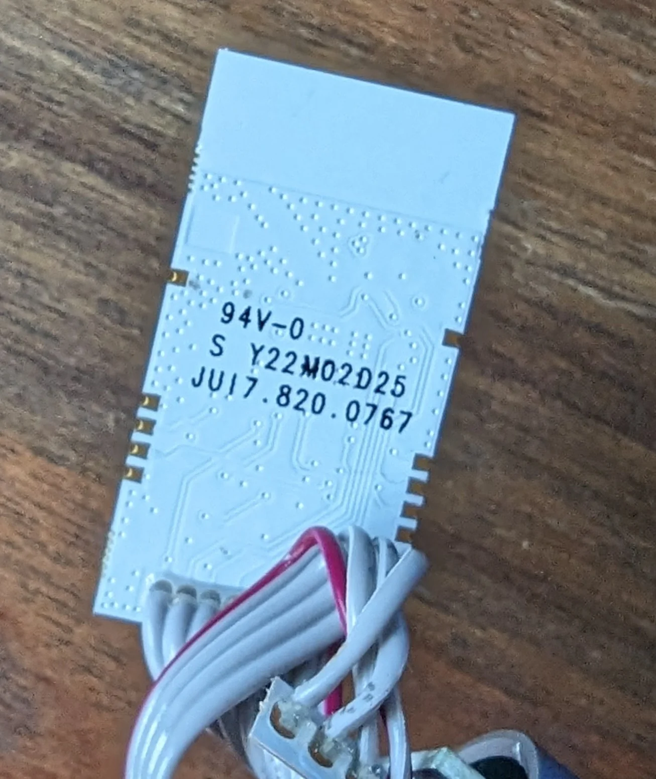
The rear of the ESP8266 module is marked with:
94V-0S Y22M02D25JU17.820.0767
The main PCB is populated with:
TLSR8368EP16: 2.4GHz RF System-On-Chip Solution for remote control puckFM24C02C: Flash rom for theTLSR83. I didn’t bother to desolder and dump this chip.- 3x ICs marked with
WRFAAin a2x5 SONpackage. I can’t find any info on these chips, but given that there are three LED channels and their proximity to power regulation circuitry, I assume that they are LED drivers.