Installing Tasmota on the Xiaomi Desk Lamp
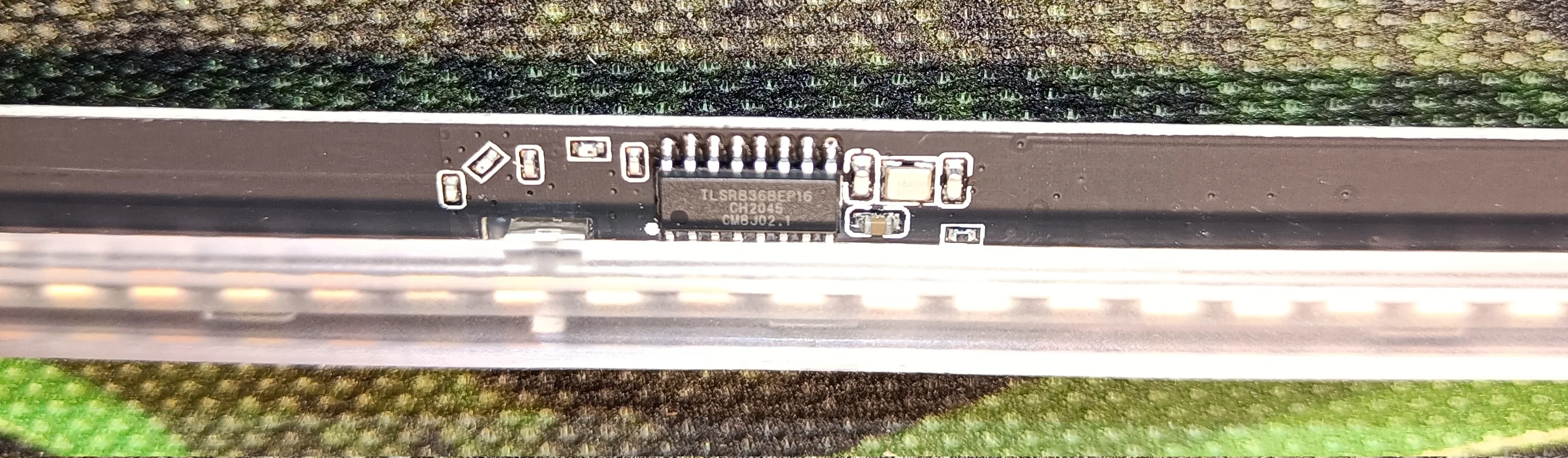
@htvekov for confirming that the MUGJD01YL variant does not contain an ESP32. It contains a TLSR8368.
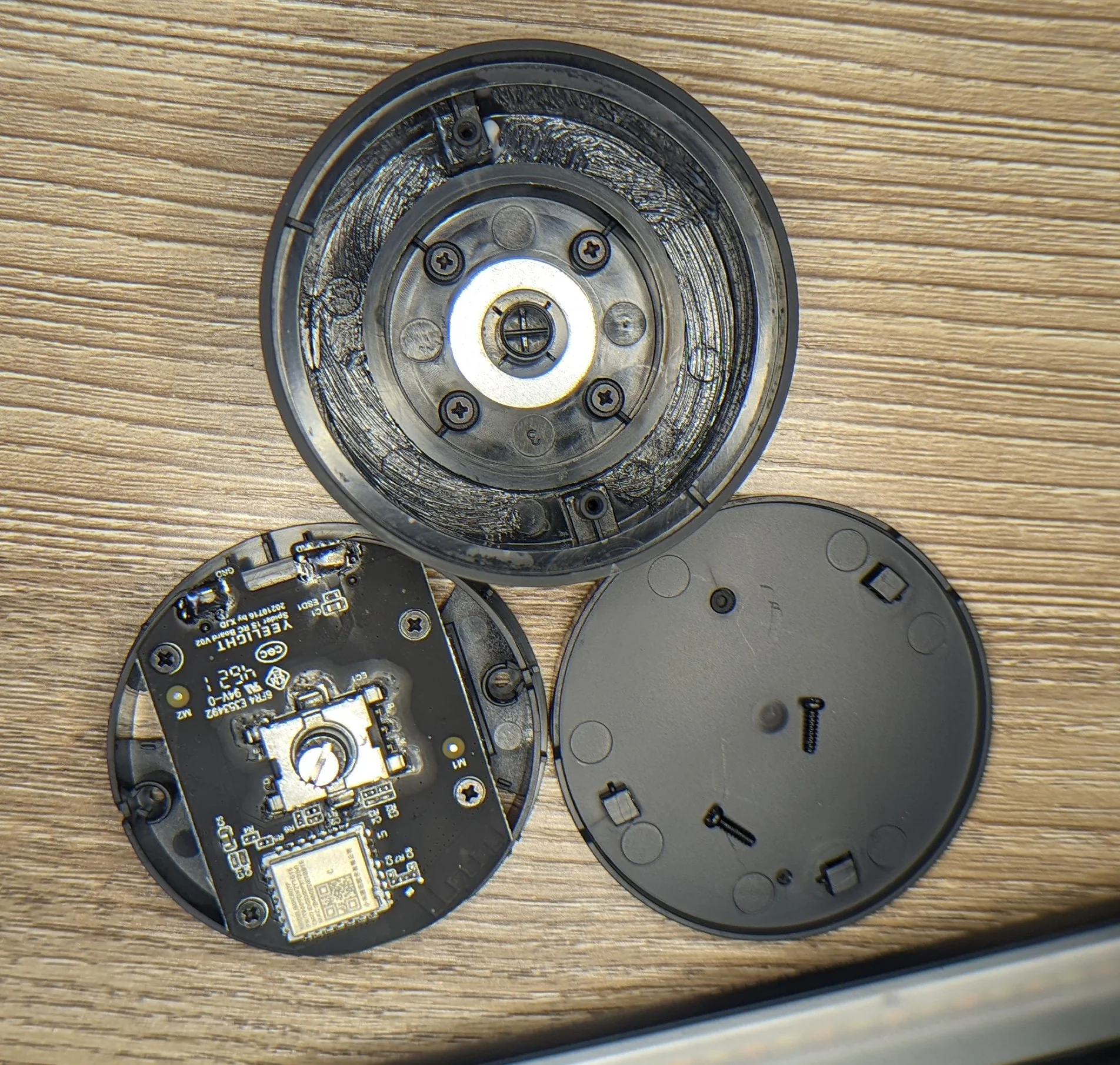
Some photos of the MUGJD01YL internals are provided below.If you’re here just for “how do I flash tasmota” bit, skip to the Tasmota section below.
I was looking for a way to light my desk my desk without screen glare. The easiest way to prevent glare on a screen is to change the orientation of the light relative to the screen either from under or behind the screen. This is not practical for ceiling mounted lights or for any floor lamps.
You can get a nearly glare free light if you mount the light to the top of the screen and direct the light away from the screen at a slight angle. Light hitting the screen and bouncing into eyes is minimized and the majority of the light ends up directed down onto the desk where it’s needed.
This isn’t a new problem; a quick search of any online retailor will reveal that there are many different options out there at all sorts of price points. As this light source would be heavily used for all sorts of work, the quality of the light is incredibly important; a high General CRI (Ra) and adjustable color temperature are requirements.
I also wanted one that had some basic remote control functions so I don’t have to reach to the top of my monitor and risk destabilizing whatever I am working on or getting finger prints on the panel. A wired remote would be simpler and thus cheaper but my desk is already too crowded with wires and cords; if the cost difference between a wired and wireless remote was marginal, opt for wireless.
After a bit of searching, I found the 2021 Xiaomi Mijia Lite Desk Lamp 1S which fit the bill exactly.

Beyond the basic puck shaped wireless remote, the listing indicated that the ’new 1s version’ could be controlled with the Xiaomi app.
🤔
Instead of some very basic 433Mhz radio, the lamp/remote probably used BTLE. In some ways, that’s even better; the lamp only has a few simple functions and those shouldn’t be that hard to reverse engineer from the Android app.
Once I know what data to send for on/off/dim/bright/ww/cw selection, I can use an ESP chip as a MQTT <-> BTLE gateway for relatively easy integration into my home automation system. Worst case, the fall back plan of using a microcontroller to emulate interacting with the remote and then integrating that microcontroller with my home automation system would work.
Once the lamp showed up, I of course opened up the remote to see what type of wireless system I was going to be dealing with.
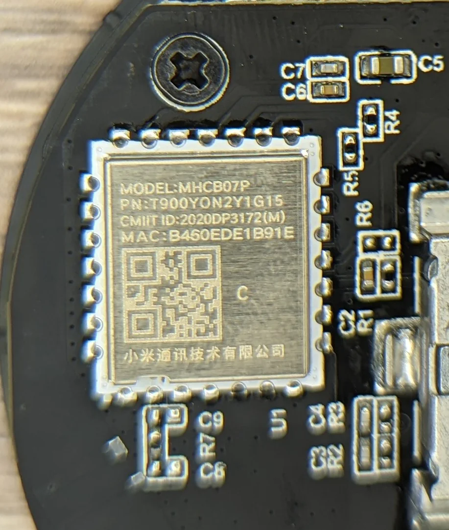
Giving the model number MHCB07P a quick google didn’t reveal much information other than confirm that it was using BTLE.
This almost certainly means that the phone app will also use BTLE to control the lamp!
If I’m lucky, I can capture the entire discovery/pair/command packets using a rooted android device and then I won’t have to bother with the puck at all.
Lamp <-> Phone
After getting the app setup, it did discover the lamp and began to walk me through the setup flow.
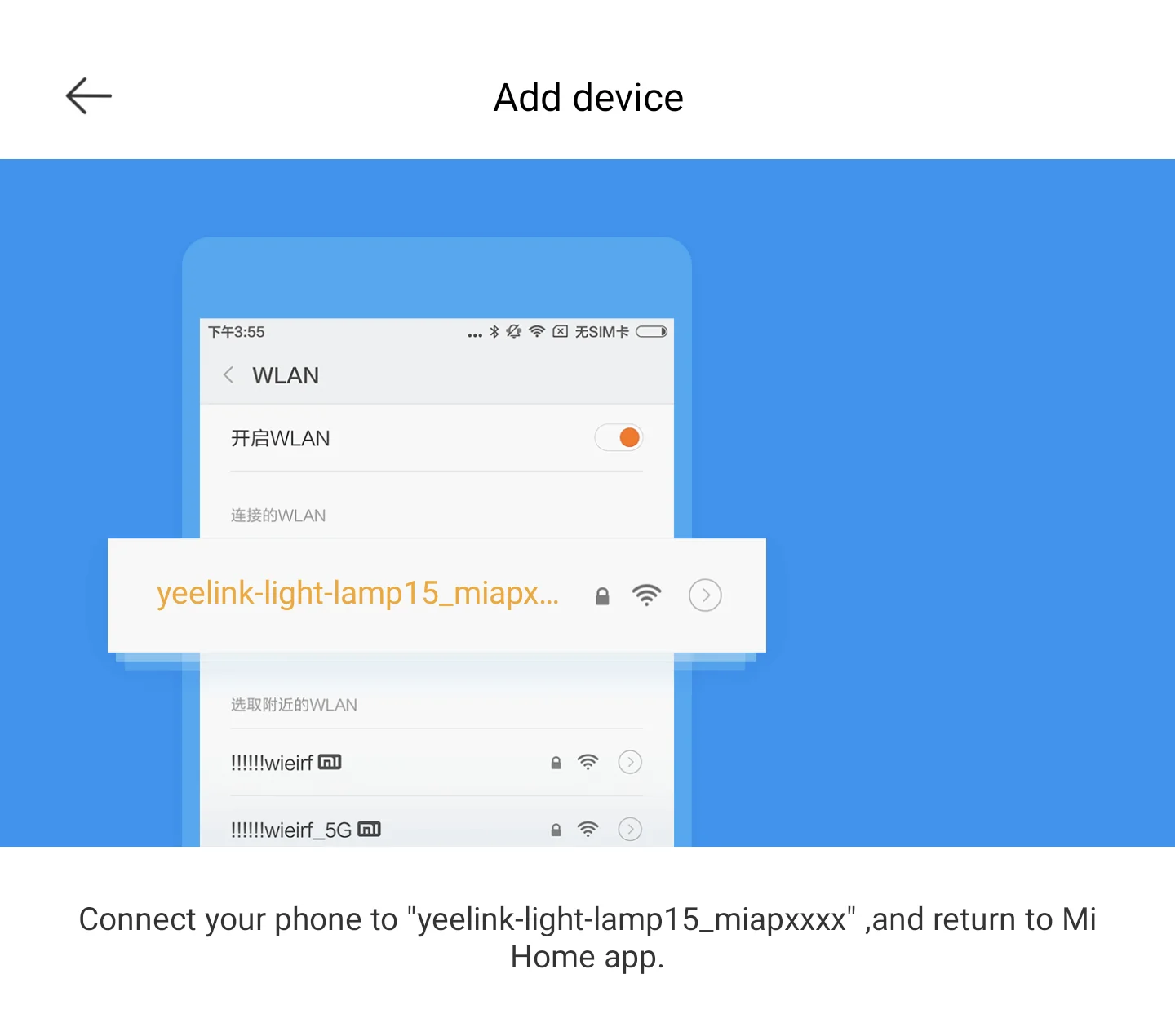
WiFi!? Really!? But why? This must be some generic screen shown for all devices, right?
Nope.
There really is a simple access point inside this lamp!
Well now I’m curious.
What could this lamp possibly need WiFi credentials for? The remote used BTLE and every conceivable phone that will also control the lamp supports BTLE… so why spend the extra money for a WiFi enabled microcontroller at all!?
ET Lamp Phone Home
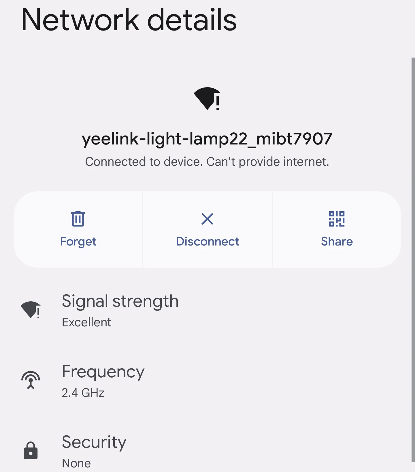
I threw the lamp behind an isolated access point and it sure is chatty…
After getting an IP address, the lamp looks up the A record for dk.io.mi.com and then attempts to open a TCP connection and send some bytes:
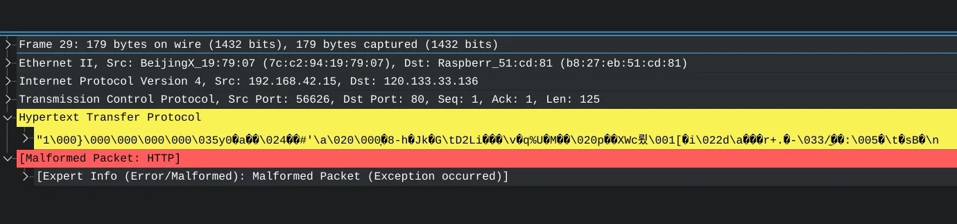
Now I’m more than a little bit curious.
Why send raw bytes to TCP/80 without at least the typical HTTP request headers? Why even use WiFi at all for a lamp? Is there no way to use my phone to control the lamp over BTLE?
Dumping the FW
Fortunately, this was pretty easy. After a cursory analysis, the dumped firmware did not appear to be encrypted or otherwise protected. I did a quick search for a few things that I hoped would show up in the dumped OEM firmware and was not disappointed:
❯ cat lamp.bin.strings | grep --ignore-case -E 'certificate|encrypt|tls|agent|http|post|get|verify|remote|{"' > interesting_strings.txt
❯ cat interesting_strings.txt| wc -l
710
🤨
Here are some of the highlights:
[I] bluetooth_remote_double_click
[E] %s: verify root cert is not valid! (%s,%d)
[W] %s: Fail to get gatt db from connection %04x, ret = %d  (%s,%d)
[E] %s: mbedtls_ecdh_calc_secret error %d (%s,%d)
miio_signature_verify
[E] %s: -->login verify send failed. (%s,%d)
-----BEGIN CERTIFICATE-----
[E] %s: https need root cert. (%s,%d)
User-Agent: MIoT
http://dlg.io.mi.com/v1/ot/upload
[W] %s: httpdns new resolve start failed, %d (%s,%d)
There’s a lot more interesting things in the dump but they’ll have to wait for another day as immediately after getting eyes on the PCB, I saw an ESP32 chip!
A change of plans
Reverse engineering the firmware to figure out how/why the phone method of remote control was different from the remotes’ method no longer really mattered. An ESP based chip means Tasmota or ESPHome should be possible.
If I could get either of those alternative firmwares running on the lamp, then cluttering up the desk with yet another remote and/or hacking MQTT support into the lamp via the remote was no longer necessary!
Teardown
I did this teardown the hard way and damaged more of the lamp than necessary. Some of the photos below reflect this.
Now that I know how it all is meant to come apart, you will hopefully have an easier time and incur less damage!
The lamp
A closer look at the marked device information before we move into the lamp. The ESP that we will soon flash with Tasmota is just behind this product information.
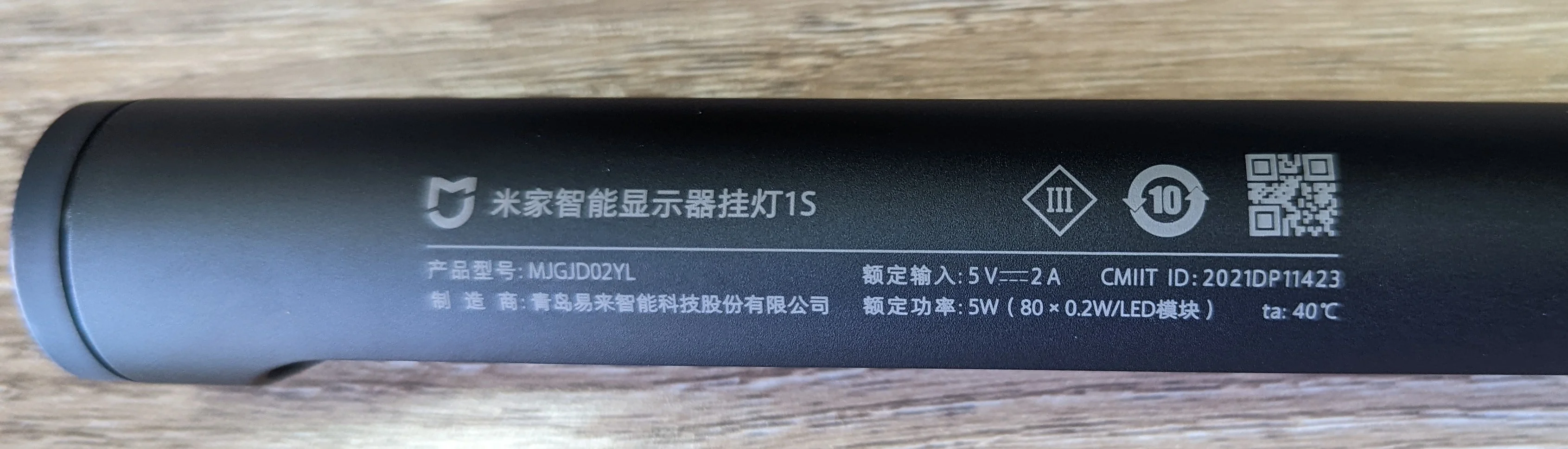
Product info and regulatory markings
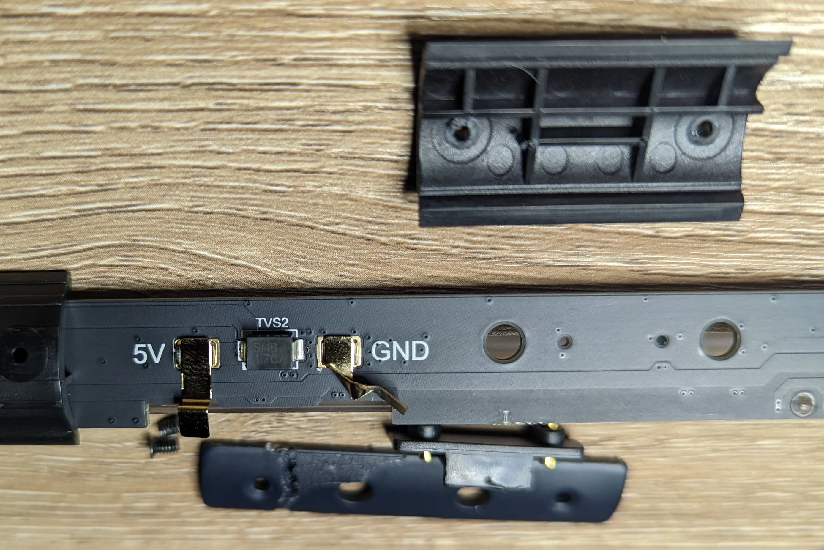
Locate the small rectangle shaped protrusion from the lamp tube that mates with the magnetic mount. The protrusion has two small pogo pins on it. You can see the protrusion in the middle of the tube facing the coiled USB power cable:
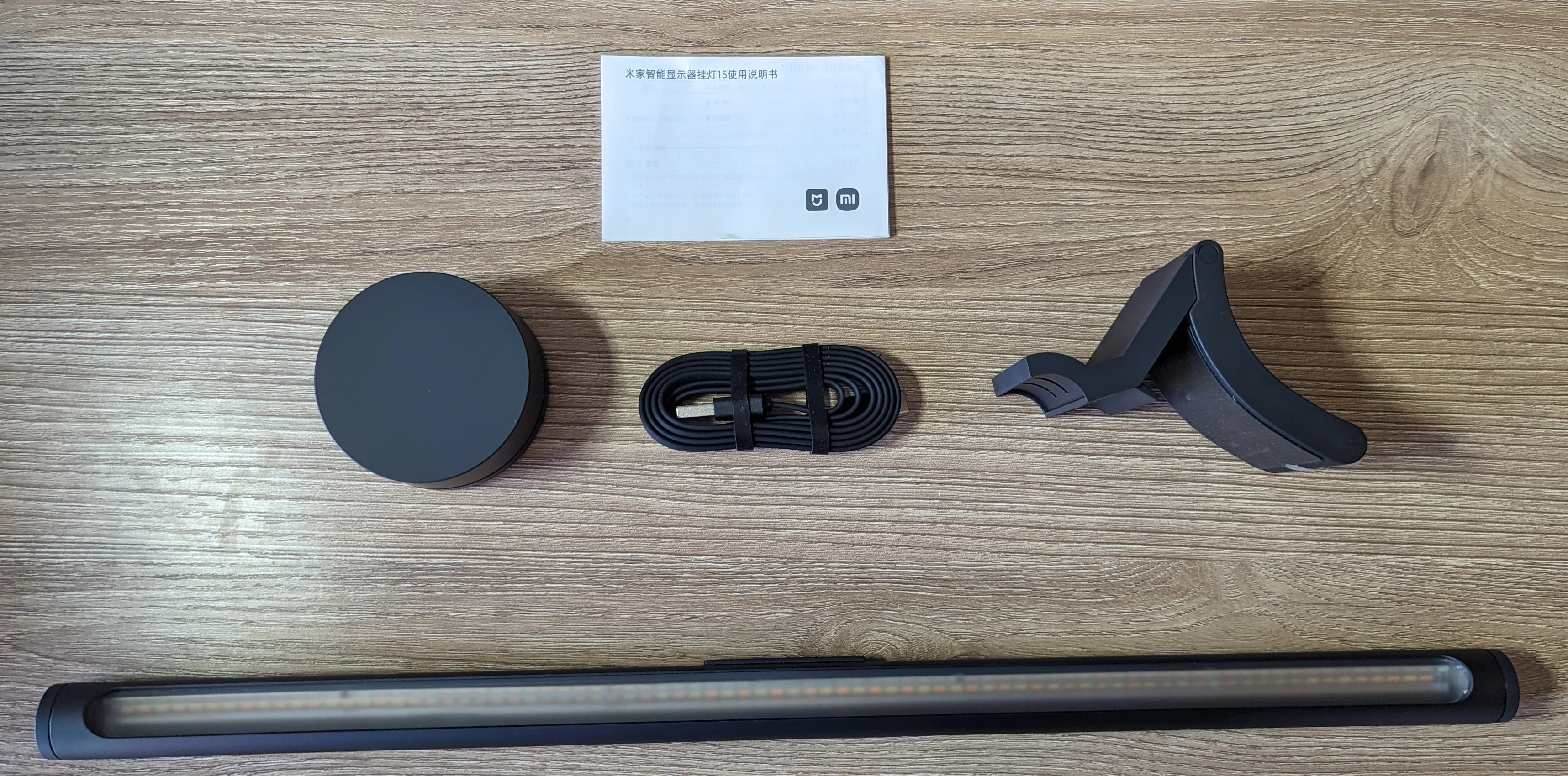
Everything that came in the box
With the protrusion facing you, locate the plastic cap closest to the product information. This should be plastic cap on the left side of the tube.
Use non-marring pliers or similar to grip the plastic cap and twist with enough force to break the glue. Do not twist more than a few degrees! The plastic cap has some features that will come into contact with and could damage the PCB if rotated too far!
Use a razor blade or similar to peel back the grip-tape sticker on the protrusion. If you’re careful and manage to remove the sticker in one piece you might be able to re-apply it during reassembly. The lamp functions fine without the sticker, though.
Underneath the sticker will be two small philips screws. Remove them and the metal protrusion and small plastic part containing the two pogo pins should come free. Set these aside.
Gently remove the clear plastic diffuser from the lamp tube and set aside.
The matte finish on the interior side of the diffuser is a fingerprint magnet. Consider using gloves for this step.
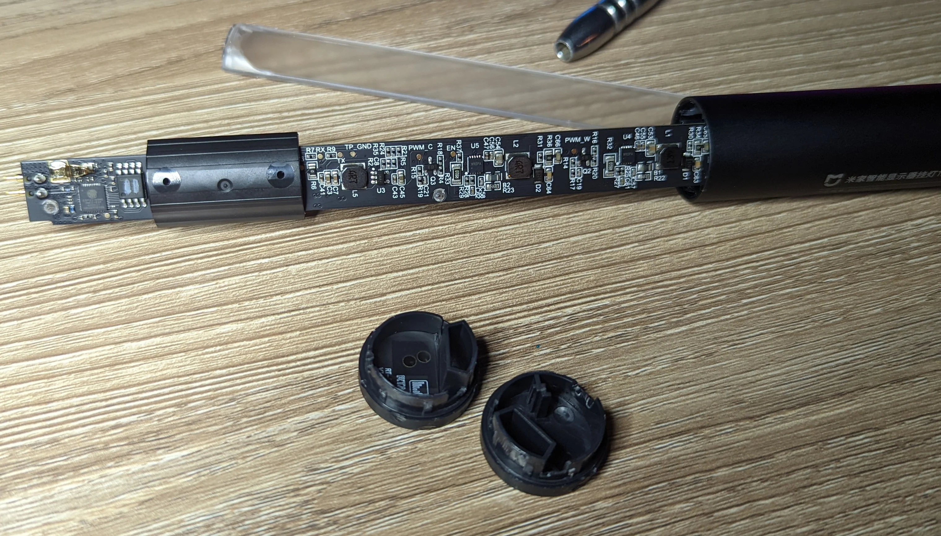
Carefully slide the PCB out of the aluminum tube. Be mindful of the two spring like contacts on the back of the PCB that mated with the pogo pins!
You can see the small black plastic bracket holding the pogo pins and the protrusion bit with some of the grip-tape still attached:
If it feels like you're using too much force to open the lamp... you probably are!
If you try to remove the PCB without first detaching the pogo pins, you’ll damage one or both of the spring contacts that mate the PCB to the pogo pins!
You don’t want your GND spring to look like mine!
Before realizing that the pogo pins could be removed from the lamp, I removed both caps and tried push/pull the PCB out.
The PCB is supported inside the tube with a few black plastic ‘sleds’ which are heat-staked on to the PCB.
The ‘sled’ closest to the ESP partially covers the 3V3 test point.
Rather than use a dedicated 3V power supply during flashing, I found it easiest to use this pin to bring the EN pin up high.
If you’re going to use the 3V3 test pin instead of a dedicated external power supply, you will probably want to remove the ‘sled’ to get easy access to the test point.
You can do this with some flush-cut snips.
Be careful to not scratch the solder mask / PCB with the sharp edges of the snips
The sled isn’t technically required for re-assembly but it’s pretty easy to re-attach to the PCB with some hotglue. Discard it at your peril!
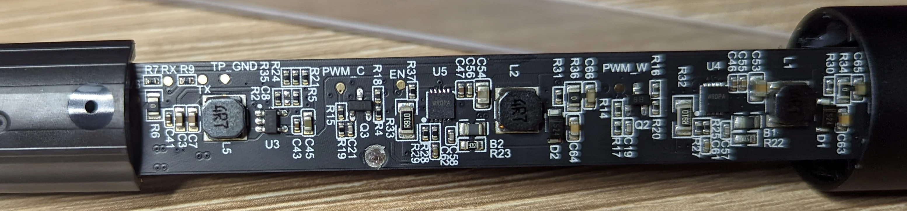
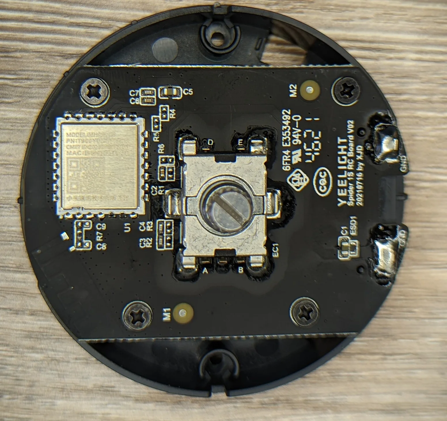
Here’s a closeup of the PCB with most of the test points labeled.
You can see the 3V3 test point immediately to the left of R6 in the shadow of the ‘sled’.
Repeat these steps in reverse order to re-assemble the lamp.
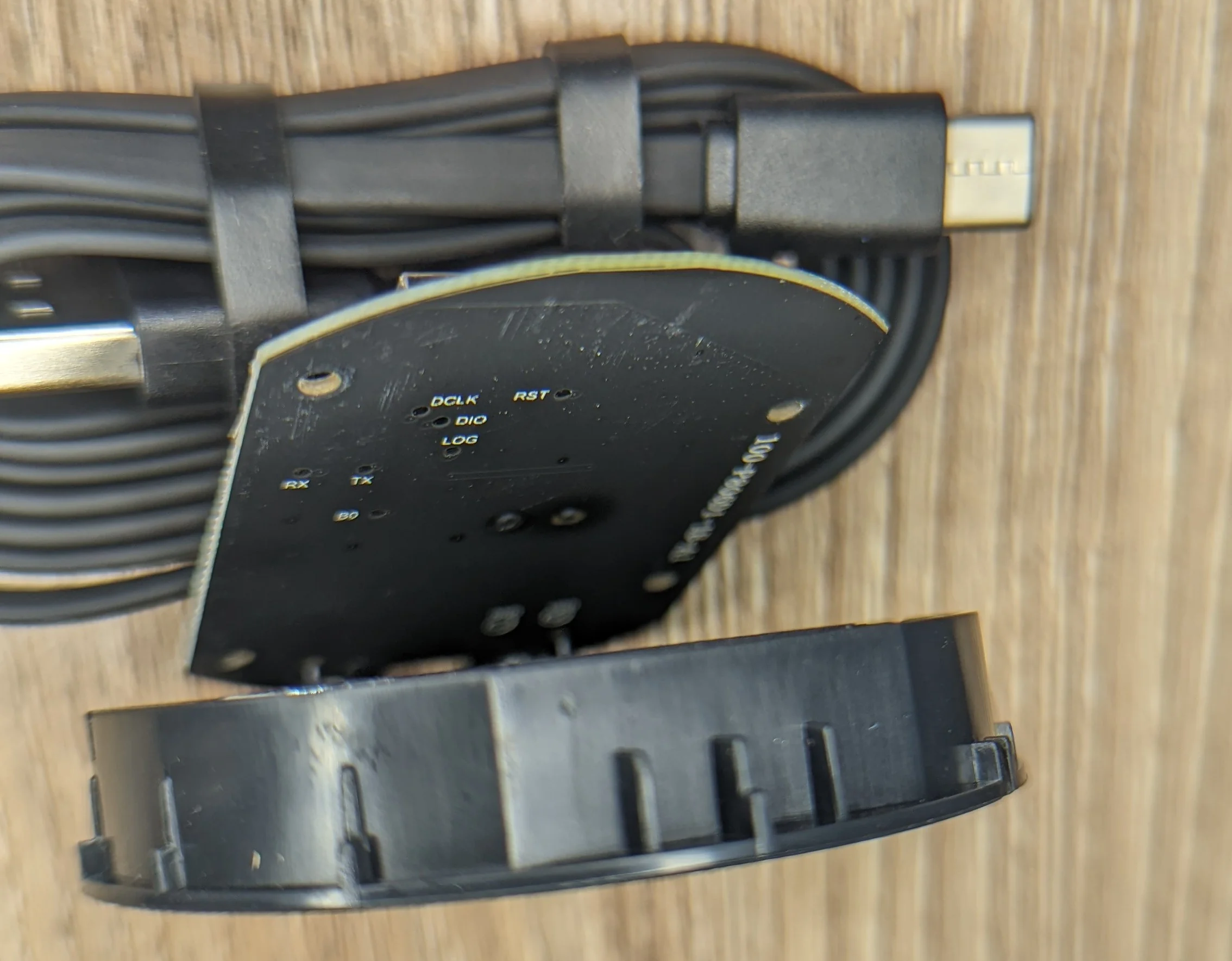
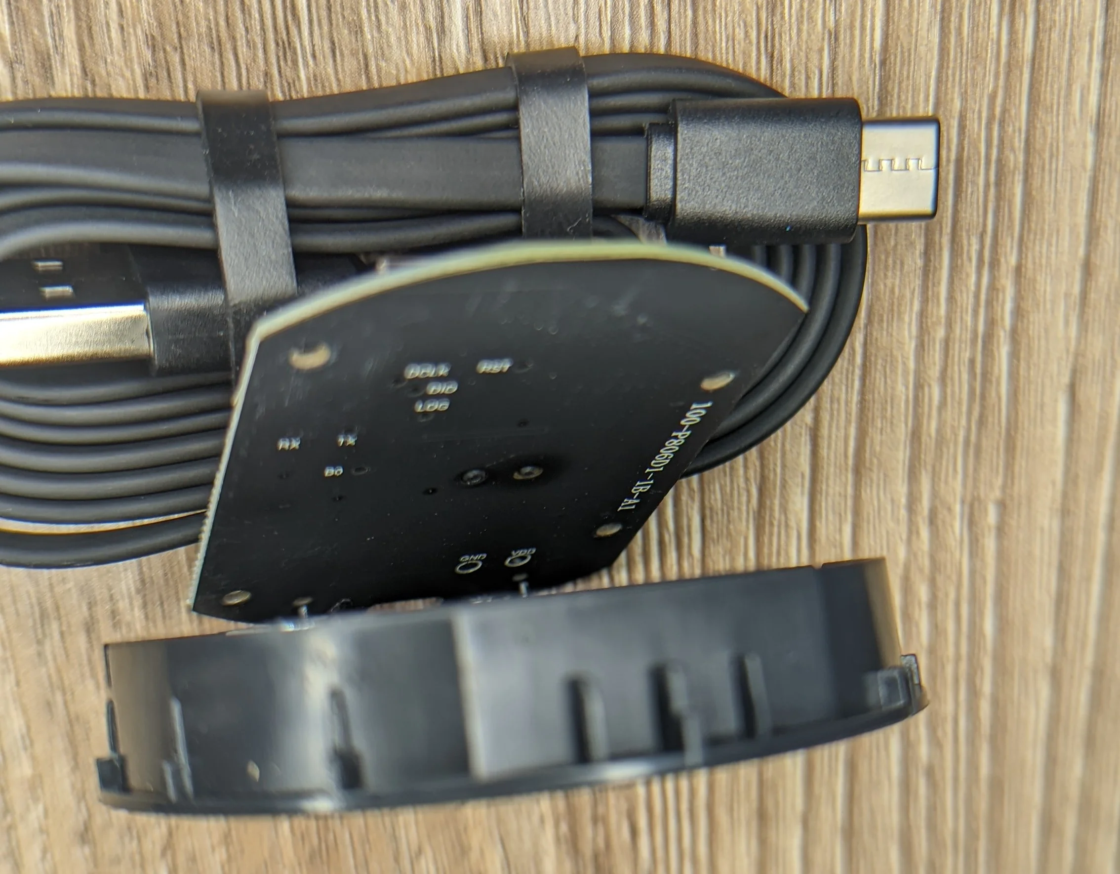
The puck
Fortunately, opening up the remote is not difficult.
Remove the two philips screws under the bottom cap.
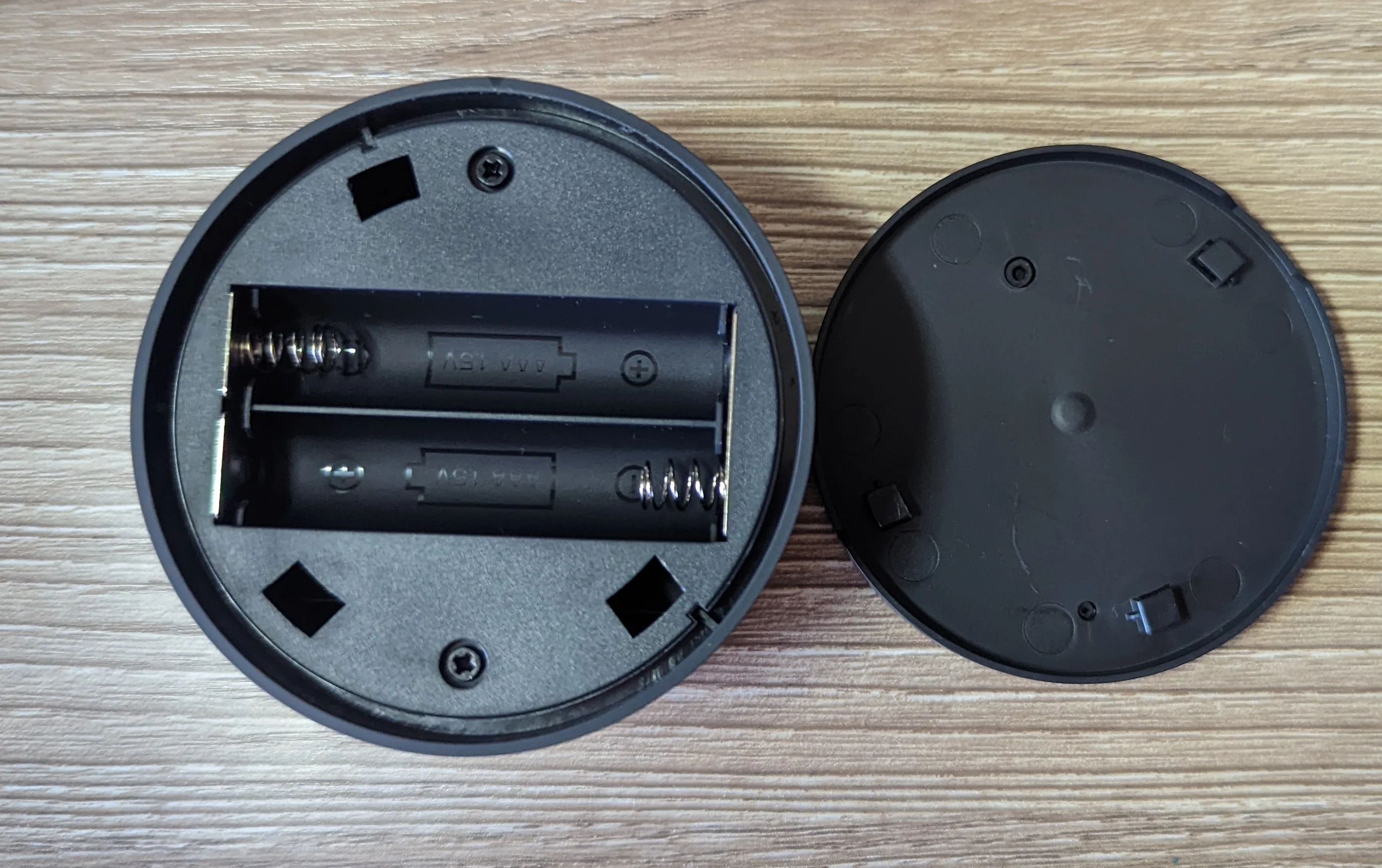
The main body / rotary knob lifts away from the midframe.
Like with the lamp PCB, there are a few test points:
Tasmota
It is likely that both the WW and CW LEDs will briefly light up during the flashing process. When this happens, you will draw more current than a typical USB <-> Serial adapter can provide. At best you’ll cause a brownout and the flash will be interrupted.
Use a dedicated 5V supply that can provide at least 10W of power while flashing the lamp! Make sure that the GND wire from your serial programmer and the GND wire for your dedicated 5V@2A/10W supply are tied together or you will likely destroy some of the electronics on both the lamp, your serial adapter and possibly your computer!
Having said all that, it’s totally worth it:
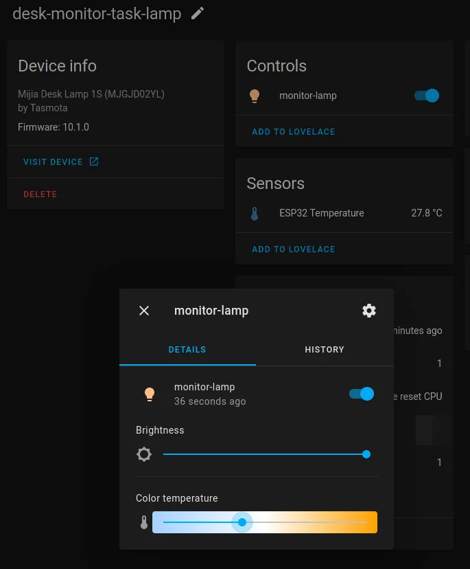
When all is said and done, the lamp is easily integrated and controlled with Home Assistant
Flashing
tasmota32solo1 version!Solder wires to the usual RX, TX, GPIO0 and GND test points.
The GPIO0 test point is the test point nearest to the ESP32 chip; directly off the bottom right corner.
I used some solid-core cable from a length of cat5 cable but any similarly high gauge wire will work.
Solder a jumper between the EN and 3V3 test point. I used a small yellow wire for this.
The solid blue wire attached to GPIO0 and the blue/white wire attached to GND are joined together just out of frame.
The ESP will not boot into programming mode unless GPIO0 is tied to ground.
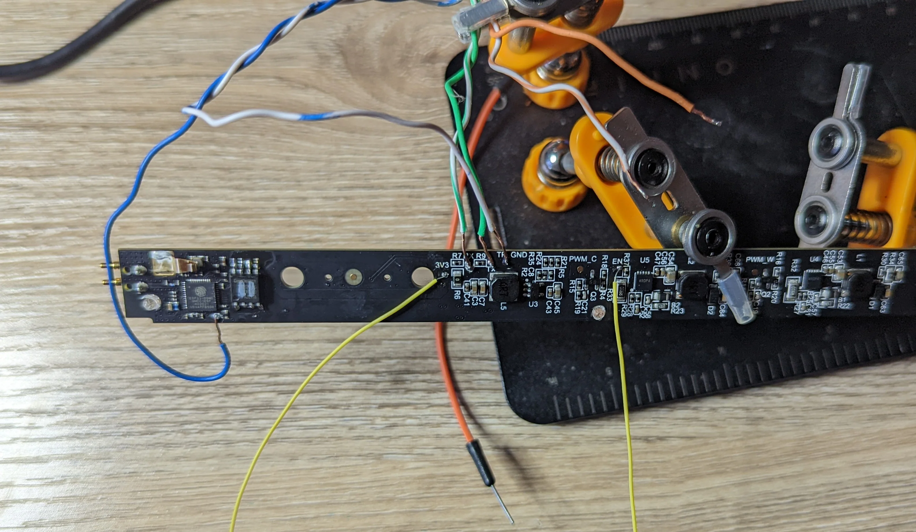
Leads from a dedicated 5V power supply are attached to the main contacts with reg/green alligator clips
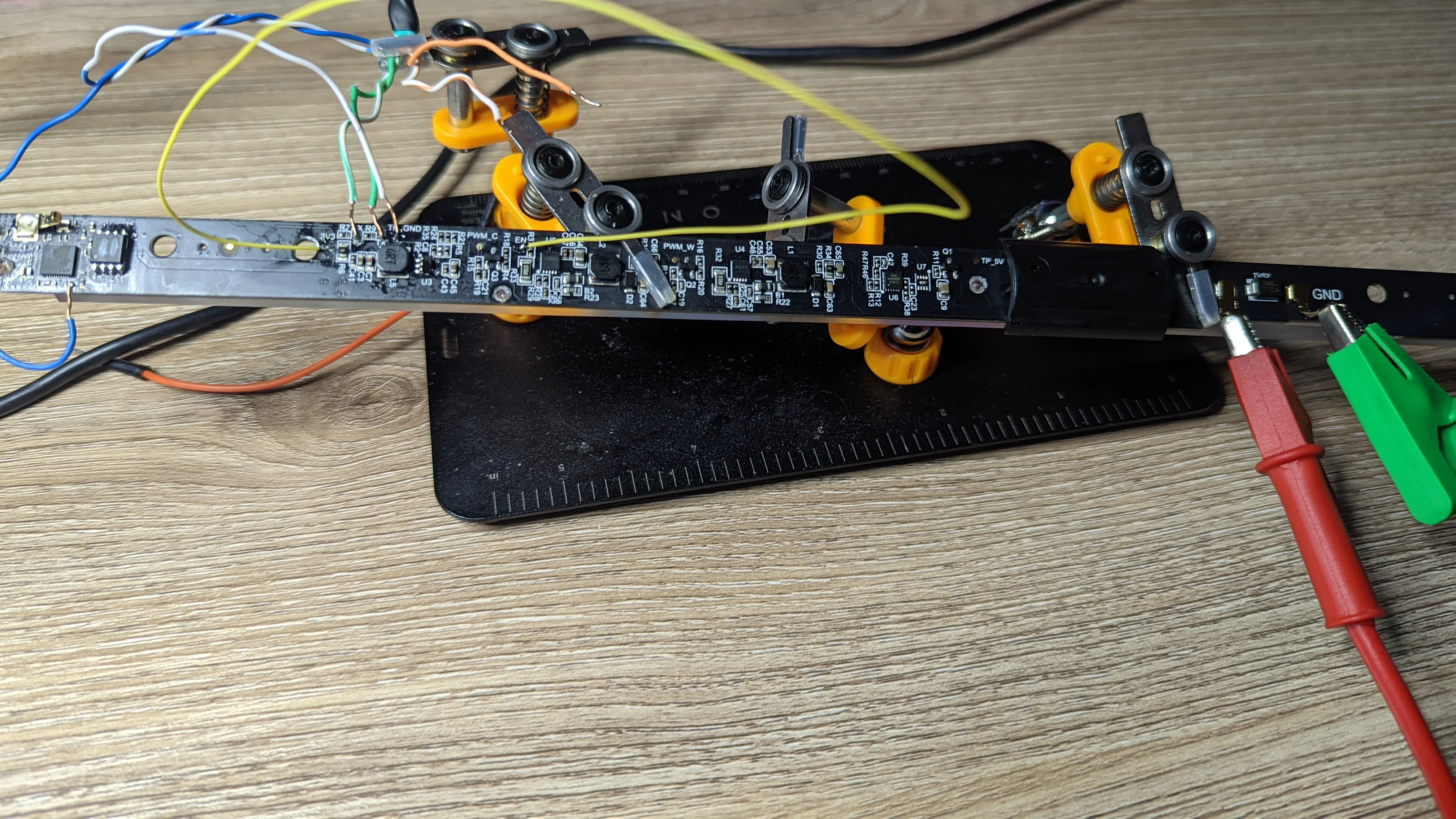
After confirming that each point is soldered sufficiently and wired to the correct pin on your USB <-> Serial programmer, turn the dedicated power supply on and you should be able to flash.
❯ esptool.py --chip esp32 --port /dev/ttyUSB0 --baud 921600 --before default_reset --after hard_reset write_flash -z --flash_mode dout --flash_freq 40m --flash_size detect 0x1000 bootloader_dout_40m.bin 0x8000 partitions.bin 0xe000 boot_app0.bin 0x10000 tasmota32solo1.bin
esptool.py v3.2
Serial port /dev/ttyUSB0
Connecting.....
<...>
Stub running...
Changing baud rate to 921600
Changed.
Configuring flash size...
Auto-detected Flash size: 4MB
Flash will be erased from 0x00001000 to 0x00004fff...
Flash will be erased from 0x00008000 to 0x00008fff...
Flash will be erased from 0x0000e000 to 0x0000ffff...
Flash will be erased from 0x00010000 to 0x00157fff...
Compressed 15536 bytes to 10862...
Wrote 15536 bytes (10862 compressed) at 0x00001000 in 0.4 seconds (effective 353.8 kbit/s)...
<...>
Hash of data verified.

Leaving...
Hard resetting via RTS pin...
Turn off the dedicated 5V supply and desolder the GPIO0 wire and the 3V3 <-> EN jumper.
Leave the RX, TX, and GND wires in place so you can easily check the boot logs to confirm Tasmota flashed OK:
❯ screen /dev/ttyUSB0 115200
ets Jun  8 2016 00:22:57

rst:0x1 (POWERON_RESET),boot:0x13 (SPI_FAST_FLASH_BOOT)
configsip: 0, SPIWP:0xee
clk_drv:0x00,q_drv:0x00,d_drv:0x00,cs0_drv:0x00,hd_drv:0x00,wp_drv:0x00
mode:DOUT, clock div:2
load:0x3fff0030,len:184
load:0x40078000,len:12352
load:0x40080400,len:2912
entry 0x400805c4

00:00:00.002-228/73 HDW: ESP32-S0WD-OEM
./components/esp_littlefs/src/littlefs/lfs.c:1071:error: Corrupted dir pair at {0x0, 0x1}
00:00:00.777-231/73 UFS: FlashFS mounted with 312 kB free
00:00:00.782-231/73 CFG: Use defaults
00:00:00.893 QPC: Reset
00:00:00.941 BRY: Berry initialized, RAM used=3849
00:00:00.950 BRY: no 'preinit.be'
00:00:00.963 Project tasmota - Tasmota Version 10.1.0(tasmota)-2_0_1_1(2021-12-08T14:50:34)
00:00:00.984 BRY: no 'autoexec.be'
00:00:00.243 WIF: WifiManager active for 3 minutes
00:00:01.200 HTP: Web server active on tasmota-197907-6407 with IP address 192.168.4.1
After confirming a successful flash/boot, you can continue to configure Tasmota via the serial console or just power off and de-solder all wires and finish configuration after you re-assemble.
Templates
The ESP32 controls the lamp via 3 GPIO pins:
GPIO04: Global light enable/disable.GPIO19: Cold White channelGPIO21: Warm White channel
Irrespective of what the WW or CW channel are doing, there will be no light if GPIO4 is not high.
This means you have two choices for how to configure the GPIO.
Tasmota will disable both GPIO19 and GPIO21 when the light is switched off so there really is no need for independent control via GPIO4.
This template keeps GPIO4 high and relies on Tasmota setting to fully off to shut the light off.
Most people should use this template.
{"NAME":"Mijia Desk Lamp 1S (MJGJD02YL)","GPIO":[0,0,0,0,3840,0,1,1,0,0,0,0,0,0,0,416,0,417,0,0,0,0,0,0,0,0,0,0,0,0,0,0,0,0,0,0],"FLAG":0,"BASE":1,"CMND":"DimmerRange 45,255"}If, for some reason, you want to control the global on/off (GPIO04) independently of the WW/CW channels, use this template:
{"NAME":"Mijia Desk Lamp 1S (MJGJD02YL)","GPIO":[0,0,0,0,224,0,1,1,0,0,0,0,0,0,0,416,0,417,0,0,0,0,0,0,0,0,0,0,0,0,0,0,0,0,0,0],"FLAG":0,"BASE":1,"CMND":"DimmerRange 45,255"}If you do not need dimmer control and only need full on/off control, you can adjust the module so GPIO{04,19,21} are always high, low or simple on/off outputs by configuring them to be of type Relay instead of PWM outputs.
Dimmer Range
In testing, extremely low brightness values for both the WW and CW channel had some undesirable behavior:
- Values lower than ~30 didn’t light at all
- Values between 30-35 caused unpleasant flicker
- Values lower than ~40 would also cause flicker when attempting to light the WW and CW channels together
For this reason, a DimmerRange of 45-255 is suggested.
Tasmota will let you dim the light as low as possible without flicker.
Your lamp, eyes and needs will differ so feel free to see if a lower dimmer value will work for you by unlocking the full dimmer range with DimmerRange 0,255 and then playing with the ct and dimmer commands to find the lowest tolerable brightness for your needs.
That is why you see the DimmerRange 45,255 command in the above templates.
PCB/IC Markings
Some of the interesting ICs and PCB markings
Lamp
- PCB is labeled
Yeelight Spider 1S V06,20210714 by XJD,94V-0,Y Y21M09D13,JUl 7.820.0874-1 - PCB has a QR code / sticker with
WF-E32-RWY1,Spider1S, and the device mac address SGM4065: Over-Voltage Protection IC and Li+ Charger Front-End Protection IC with LDO Mode- Some DFN-10 package that is marked with either
WRDPAorWRQPAorWR0PA. It’s a little hard to tell as the markings are super faint and I can’t get them super clear even with high contrast / inverted color image filters. There are several of them with identical circuitry through the length of the board so this IC is some sort of pwm dimmable constant current LED driver. ESP32-D0WD: the star of the showGD25Q32(B): a 4096 kB SPI flash chip- The lamp body is marked with
CMIT ID: 2021DP11423
Remote
- PCB labeled with
100-P806D1-1B-A1,Yeelight Spider 1S RC Board V02,20210716 by XJD MHCB07P. This is marked on the tiny BTLE module inside the remote. Not too many search results show up.CMIT ID: 2020DP3172(M)
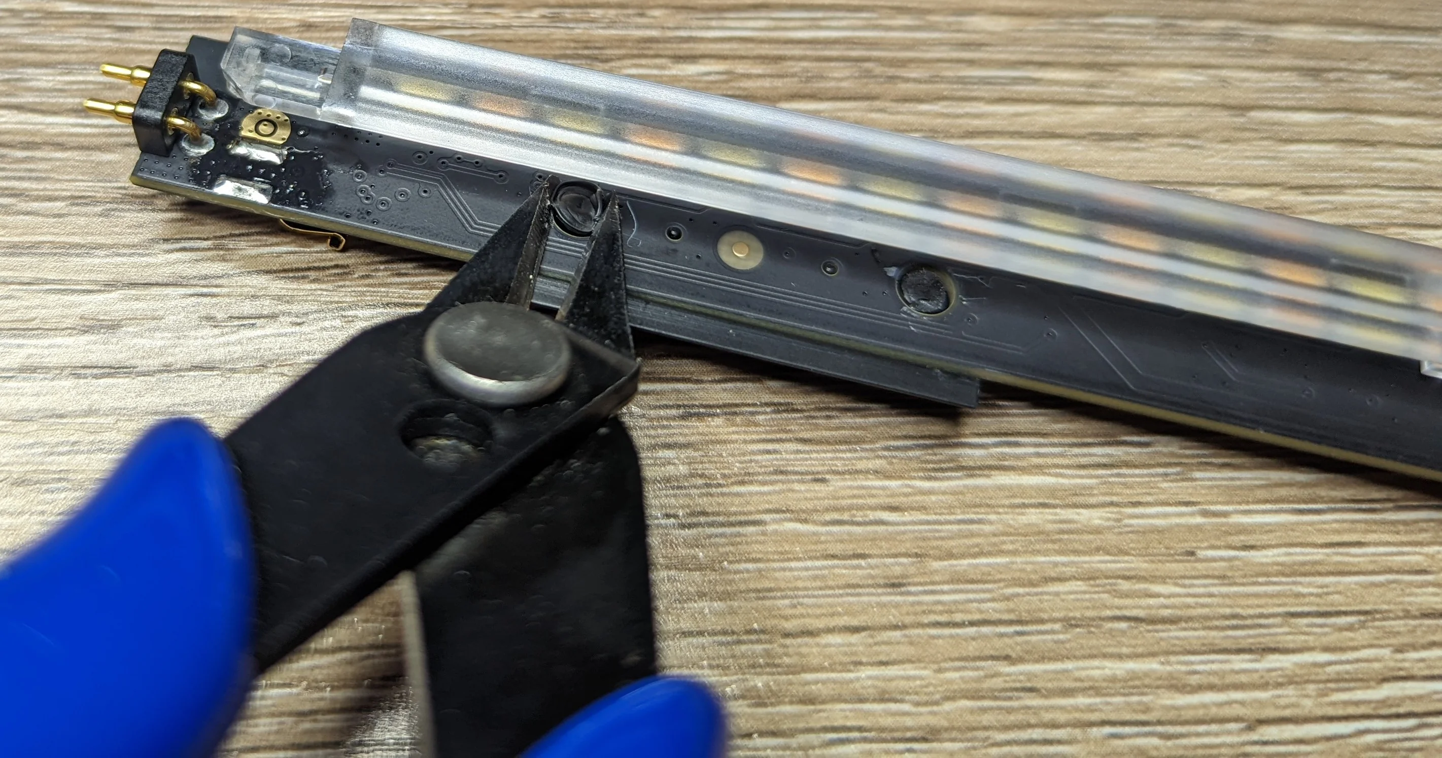
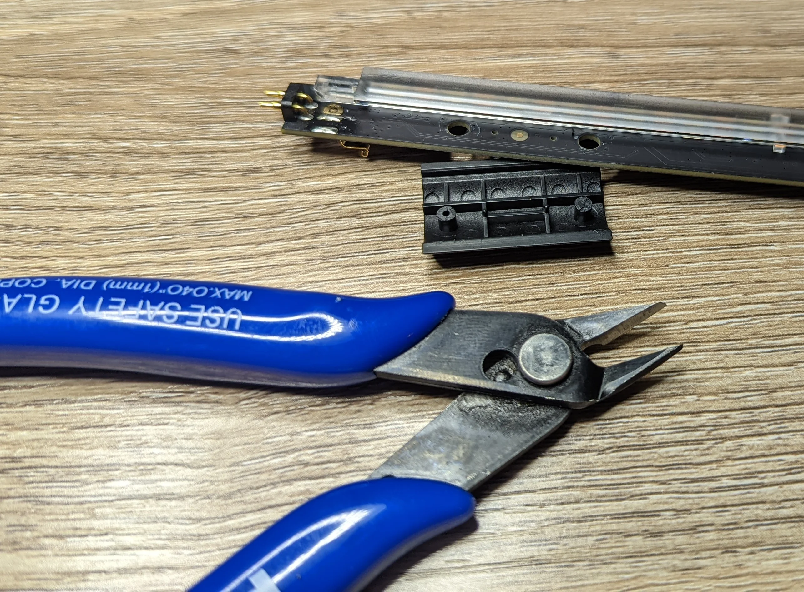
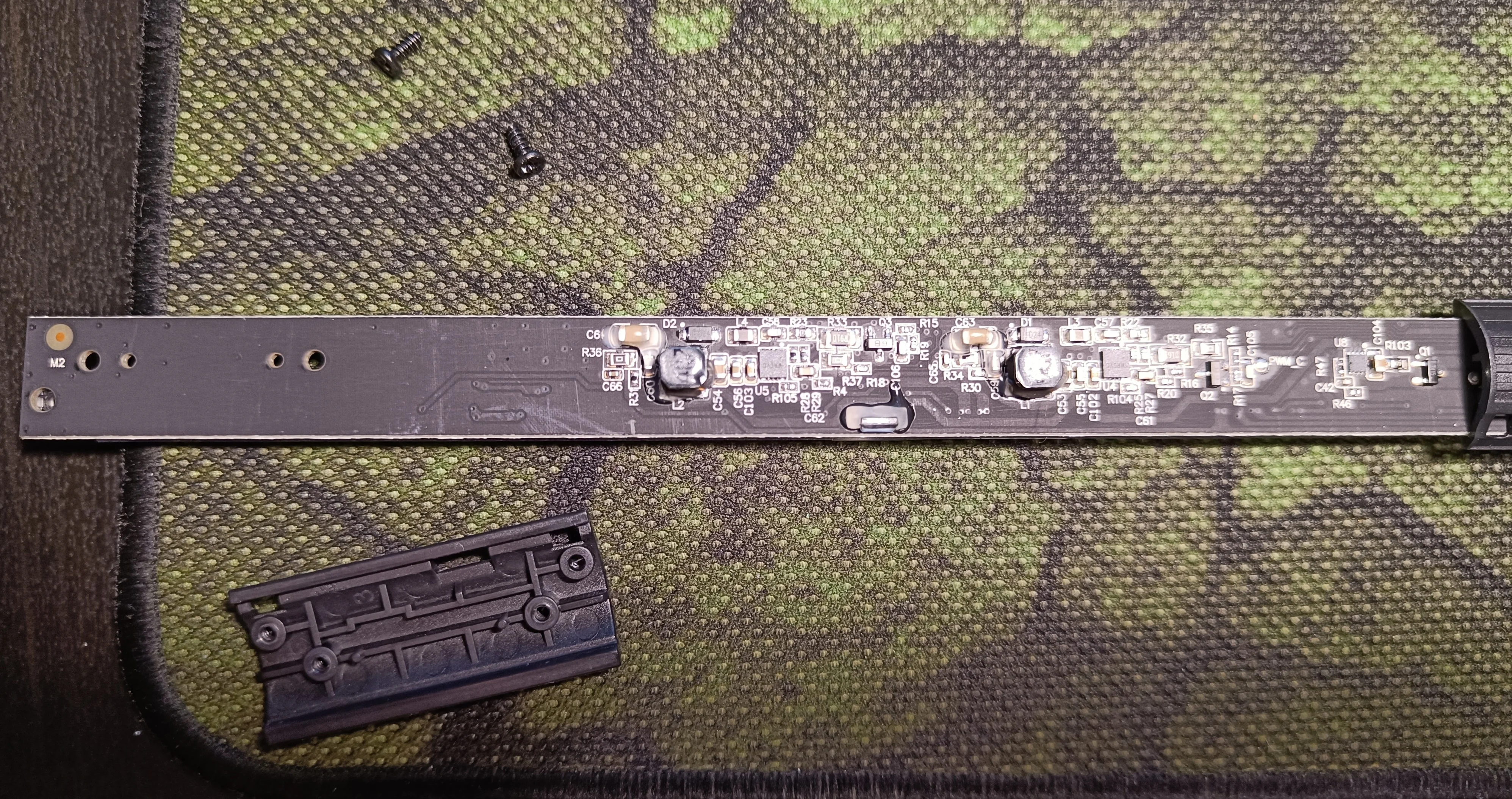
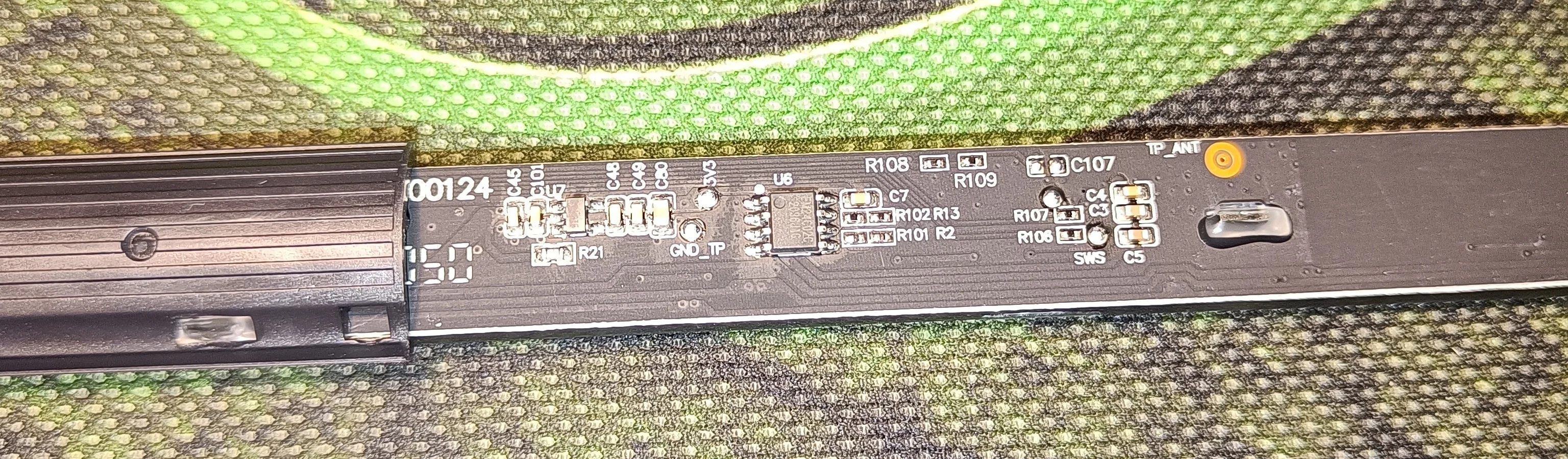
MUGJD01YL
Product details for the lamp that can't be converted to run Tasmota.
Courtesy of @htvekov The PCB is held in the tube with similar plastic 'sleds'. They are secured with screws rather than heatstake so they are easier to remove. The move to heatstake in the revised edition was likely to reduce costs.
Courtesy of @htvekov Courtesy of @htvekov Courtesy of @htvekov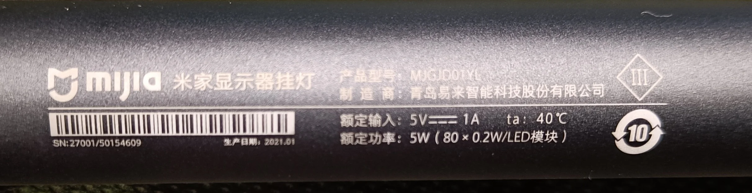
ESPHome
While putting together the “update” to this post, I figured I should update this post with the configuration that I used for ESPHome:
##
# This is an ESPHome port of https://templates.blakadder.com/xiaomi_MJGJD02YL.html
##
esphome:
  comment: "Xiaomi Mi Computer Monitor Light Bar 1S Light (MJGJD02YL)"

# See: https://github.com/esphome/issues/issues/2955
esp32:
  board: esp32dev
  framework:
    type: esp-idf
    sdkconfig_options:
      CONFIG_FREERTOS_UNICORE: y
    advanced:
      # See: https://github.com/esphome/issues/issues/4830
      ignore_efuse_mac_crc: true

# Enable logging
logger:
  level: INFO

# The light bar has two banks of LEDs for WW/CW config
# See: https://esphome.io/components/light/cwww.html
##
light:
  - platform: cwww
    id: leds
    cold_white: out_pwm_cw
    warm_white: out_pwm_ww

    # The ali express listing indicates 2700/6500K.
    cold_white_color_temperature: 6600K
    warm_white_color_temperature: 2700K
    # Draws a little over 10W at full brightness.
    # Shouldn't be too hard for a USB power supply to handle but heat dissipation might be an
    #   issue so don't permit both WW and CW channels to both run 100%.
    constant_brightness: true

output:
  # THis is the master kill switch. This GPIO must be high for the WW/CW channels to work.
  - id: light_enable
    platform: gpio
    pin: GPIO04

  - id: out_pwm_ww
    platform: ledc
    pin: GPIO21

  - id: out_pwm_cw
    platform: ledc
    pin: GPIO19