Adding an airborne particulate mater sensor to WS3 Weather Station
A while back, I posted a small bit of code that could decode the data from the ubiquitous WS3 Weather Station and make it accessible to the amazing HomeAssistant via the wonderful ESPHome project. Since then, my weather station has been dutifully collecting data that’s been invaluable for augmenting automation that deals with indoor climate.
As the numerous wild fires in California rage on, the air quality has gone from bad to dangerous. Knowing that outside was warmer, but less humid, was no longer enough to make a smart decision about weather or not to open the windows for some cost-effective cooling. I now need HomeAssistant to be aware of how clean the outside air was before making the decision to pipe in outdoor air.
This post covers two things:
- A small update to the existing WS3 -> ESPHome -> HomeAssistant bridge code to take advantage of the WS3s’ support for the ubiquitous
PMS5003Tsensor. - A simple 3d-printable enclosure for deploying the particulate matter sensor outdoors
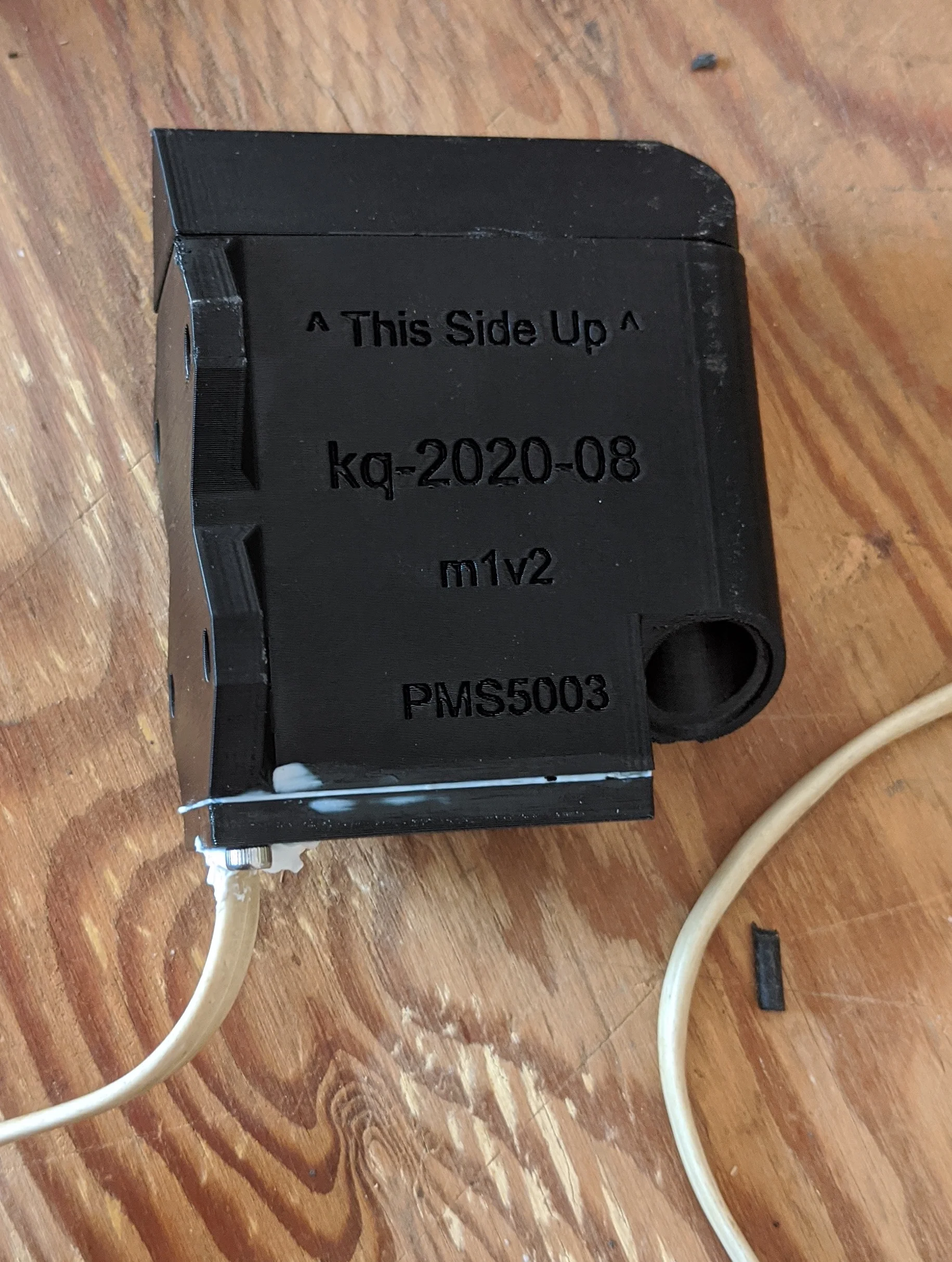
When deployed, it looks like this:

Excuse the awkward camera angle; sensor is deployed in an awkward to photograph location.
Please ignore the awkward camera angle as the sensor is deployed in a location where there’s not quite enough room for proper camera placement.
And results in graphs that look like this:
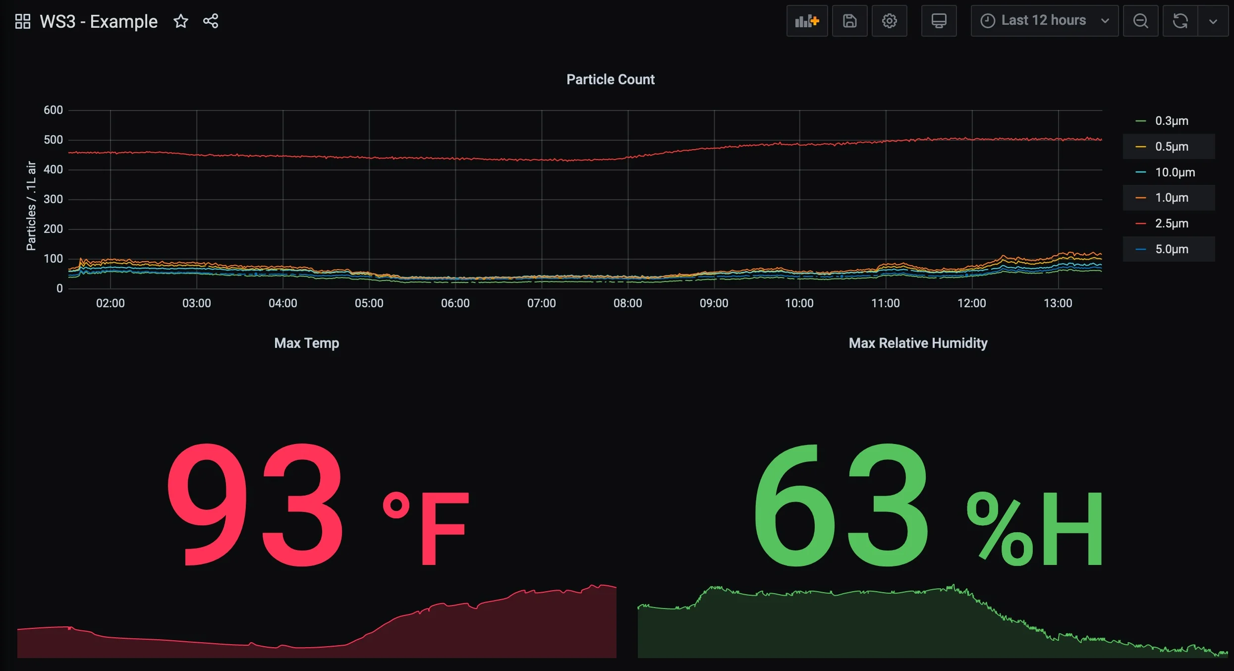
Smoke particles are between .4μm to .7μm in size... which explains the elevated red line relative to other particle sizes.
A simplified copy of this post appears on thingiverse and prusaprinters.
The enclosure
As of writing, there’s one existing enclosure for the sensor on thingiverse. Unfortunately, the enclosure does not appear to have any design features for mounting to a pole nor does it have any bug-proofing design elements. I took this opportunity to design my own that could be easily mounted, features a slanted ‘roof’ to prevent standing moisture ingress and could use standard size tobacco pipe filters to keep all but the tiniest of insects/particles out.
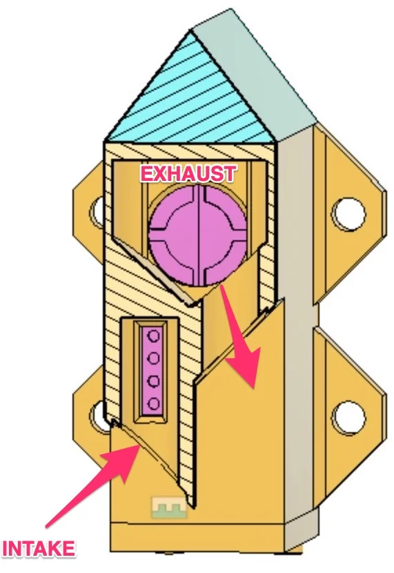
The sensor uses a small fan to draw ambient air past an infrared laser. As airborne particles cross the laser beam, they reflect a certain amount of light which can be correlated with the size of the particle. This data can then be turned into fairly accurate counts of how many particles of a given size are in the sampled air. The enclosure is a basic box with two circular air channels pointed downwards to prevent moisture ingress. The intake and exhaust ports are at staggered heights and pointed in opposite directions and to minimize the chance of recirculating the same air.
The lower port is the intake which connects to a few small holes on the front of the sensor and the exhaust port is the raised port which connects directly to the exhaust fan. If you could remove the first few mm from the front, it would look something like this:
From the side, you can see the two air channels and the few mm of room in the back for wiring. The sensor sits on a ‘pedestal’ to keep it elevated away from any moisture that may collect on the bottom of the enclosure.
The base plate/pedestal are secured to the ‘body’ with two M3 screws. I used 10mm as that’s what I had on hand, but screws between 6-12mm should work as well. The holes are sized for a M3, but any similar sized screw will work. Use a lighter or similar to heat the screw as you drive it into the plastic to create your own threads if using a larger/longer screw.
Besides the ‘pedestal’ there are a few contact surfaces that hold on to the sensor with a friction fit. The ‘ceiling’ is a few mm thick and shouldn’t permit much moisture ingress but an optional slanted roof component can be printed as an extra precaution.
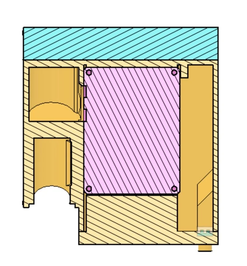
Upper and lower chambers for exhaust and intake.
While designing the enclosure, I used this PMS5003 model from Leclercq Gregory. :pray:
Printing
This is a functional part with only three small surfaces that require reasonably tight precision to properly hold onto the sensor. The SPEED setting with a .2mm layer height and a reasonable 20% infill gave me part that works and feels water tight. The walls and ceiling need to keep water out so dipping below 15% infill or otherwise using settings that wont give solid layer adhesion is not advised. I printed using ABS for durability, but PLA will probably work if you can deploy into a shaded environment.
The shroud and the base are not optional, the triangle shaped block is intended to turn the flat roof of the shroud into a slanted roof so water can’t collect. It is optional but shown below.

No raft/support when printed in this orientation.
Assemble
Briefly:
- collect materials
- press-fit the PM2.5 sensor into the enclosure
- make a wire that can interface the PM2.5 sensor to the WS3 board via RJ11
- seal everything up
- glue on mesh screens and angled roof
- plug into WS3
- flash ESPHome onto
Bill of Materials
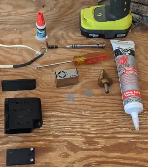
More or less everything that is needed for assembly is pictured below.

More or less everything needed to assemble.
Components:
WS3 Weather Station - Essential / Foundational
ST5003T PM2.5 Sensor - Essential / Foundational
ESP32 Device - A link to the ESP32 based device that I use but any ESP platform with a spare GPIO that can be used as a UART will work.
3/4 inch tobacco pipe screens - For bug/critter proofing the enclosure. Strongly suggested for outdoor deployments.
2x M3 x 10mm screws - Optional. The base can be glued to the shroud or any similar screw will work
Note: Where possible, I’ve used referral links. The links don’t raise the price of any item, they simply let the retailer know that I sent you and, in return, I get a small cut of your purchase. If you’re not comfortable with that, you can use a URL unwinding service to get the ‘raw’ product link and drop the attribution/commission part.
General bits:
- Superglue
- Waterproofing caulk/sealant
- Drill/Screwdriver
- Driver bit for the screws
The stepped drill bit in the above picture is not a requirement if you assemble things in the correct oder. The cable egress hole is sized for a ’typical’ 3 pair RJ11 cable plus a tiny bit of wiggle room. I needed a working cable to test the code while the parts were printing so the hole in the printed base needed to be enlarged slightly to fit the head of the cable.
Wiring
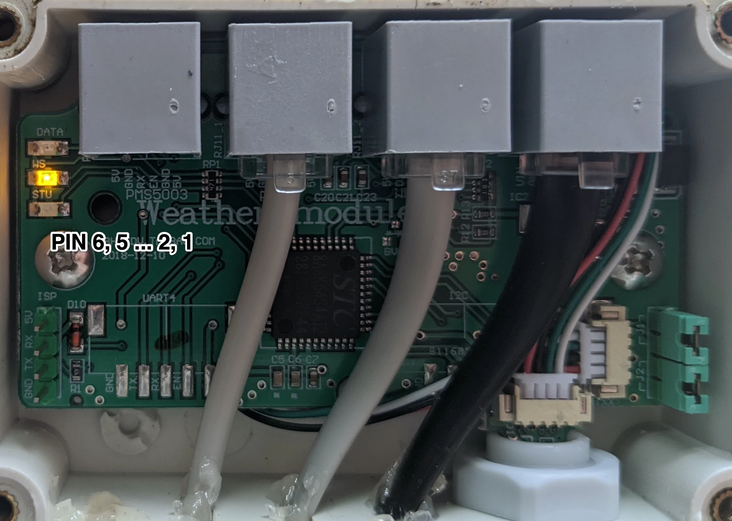
There’s no ready-made cable out there that’ll join the two devices so one must be made. Fortunately, there’s only 6 wires to deal with… 4 of them are distinct.
Sacrifice the cable that comes with the PM2.5 sensor and the RJ11 cable by cutting them in half and solder the correct wires together. The color of the wires that come in both the RJ11 cable and the PM2.5 cable are likely going to differ from the ones I used so I’ve left those details out and provided a table showing which pins are to be joined together:
| Pin # | PM2.5 Sensor Pin | WS3 Pin |
|---|---|---|
| 1 | VCC | 5V |
| 2 | GND | GND |
| 3 | SET | ENABLE |
| 4 | RX | RX |
| 5 | TX | GND |
| 6 | RESET | 5V |
| 7 | NC | |
| 8 | NC |
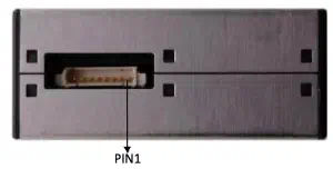
For reference, Pin 1 on both the WS3 and PM2.5 Sensor:
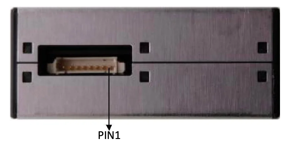
With the wiring done, the sensor just needs to be stuffed into the enclosure. Don’t forget to thread the RJ11 cable through the hole in the base plate BEFORE soldering it to the cable for the PM2.5 sensor… otherwise you’ll need that stepped drill bit! 🙃

Sensor has been press-fit into the enclosure and wire fed through the base plate.
To finish, secure the base with screws and a bit of water-proofing caulk for good measure:
I suggest waiting until the end to glue on the optional roof and waiting until just before that to glue on the optional mesh screens.
The code
Setting up and using ESPHome is outside the scope of this post but there are several good guides out there. Once you have that set up, include the ws3.h file and set up your custom sensor as shown below. A working example and more detail is over on the
github repo.
It’ll look like this:
uart:
  id: uart_bus
  # At this time, ESP does not Transmit anything to the WS3
  tx_pin: GPIO16
  rx_pin: GPIO17
  baud_rate: 2400

sensor:
  - platform: custom
    lambda: |-
      auto ws3 = new WS3(id(uart_bus));
      App.register_component(ws3);
      return {
        ws3->temperature_sensor,
        ws3->pressure_sensor,
        ws3->humidity_sensor,
        ws3->wind_speed_current_sensor,
        ws3->wind_speed_peak_5m_sensor,
        ws3->wind_direction_sensor,
        ws3->rain_fall_1h_sensor,
        ws3->rain_fall_24h_sensor,

        ws3->particles_03um,
        ws3->particles_05um,
        ws3->particles_10um,
        ws3->particles_25um,
        ws3->particles_50um,
        ws3->particles_100um,
      };
With that, check the logs from your instance of ESPHome and you should see something like this:
[D][ws3:157]: pkt_read_ok!
[D][WS3:410]: VALID! Packet: [c000s000g000t093r000p000h35b09880,050,080,088,502,056,065,*18
], Checksum: [18] chksum: [18]
[E][WS3:342]: Validating: [c000s000g000t093r000p000h35b09880,050,080,088,502,056,065]
indicating that the WS3 has detected the PM2.5 sensor and is reporting it’s readings in addition to the temperature/wind data. Then just check your HomeAssistant install for the data.
Files
For archive / posterity, all source files are included here. All files are licensed as Creative Commons Attribution-NonCommercial-ShareAlike (CC BY-NC-SA).
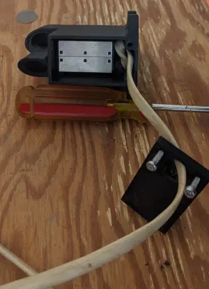
Sensor has been press-fit into the enclosure and wire fed through the base plate. 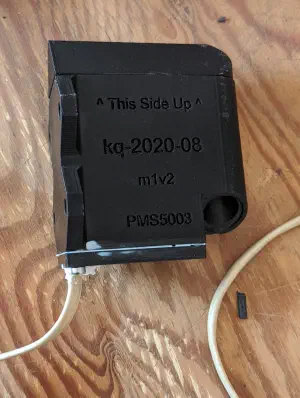
I suggest waiting until the end to glue on the optional roof and waiting until just before that to glue on the optional mesh screens. 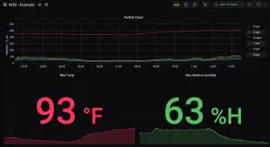
Smoke particles are between .4μm to .7μm in size... which explains the elevated red line relative to other particle sizes. 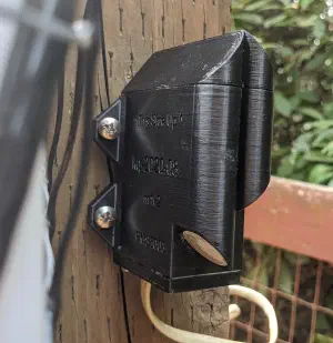
Excuse the awkward camera angle; sensor is deployed in an awkward to photograph location. - models/BASE.step: step file
- models/BODY.step: step file
- models/LID.step: step file
- models/base.stl: stl file
- models/body.stl: stl file
- models/combined.3mf: 3mf file
- models/lid.stl: stl file

More or less everything needed to assemble. 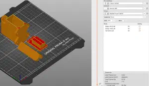
No raft/support when printed in this orientation. 
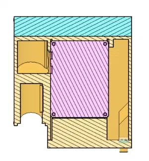
Upper and lower chambers for exhaust and intake.


