Tuya Smart Curtain Driver Robot Teardown
I am trying something new out with this post; some mix of hardware teardown and a brief product review.
Why
I was looking for a way to actuate some heavy blackout curtains.
There have been several DIY projects out there that manipulate curtains but they all appear to be relatively involved as they are often designed for a very specific type of curtain; servos that fit on the ’tilt rod’ or motors that can manipulate the pull chain… etc.
The specific curtains that I wanted to power-actuate are curtains that do not have a pull string or a set of wheels/track to facilitate their movement. Just folds of fabric hanging directly from a telescopic metal rod.
After a quick review of hte existing commercial solutions for my application/style of curtains, it became clear that they all work in about the same way: some battery powered motor mechanically couples to the curtain rod and moves along the rod dragging / pushing the curtain as it does so.
Since they all more or less use the same design, I figured that most of the differentiation between products would be in the software side of things. No product immediately stood out as having local Home Assistant integration so it didn’t matter which product I selected; I will inevitably have to do some reverse engineering / hacking to get local Home Assistant integration.
I selected the Tuya Smart Curtain Driver Robot because:
- Cheap
- Appeared to use USB-C for charging
- I was vaguely aware that TuYa was pumping out a ton of ESP8266 based hardware and hoped that I’d find the familiar microcontroller inside.
Below is a collection of photos and some thoughts that are - roughly - what I wish I had been able to find when doing the product research. If I had found the equivalent of this post while doing my research, I would have been able to save myself a purchase!
What
Searching for rod-based curtain actuators will turn up a ton of results. A fair number of them use product images very similar to these:
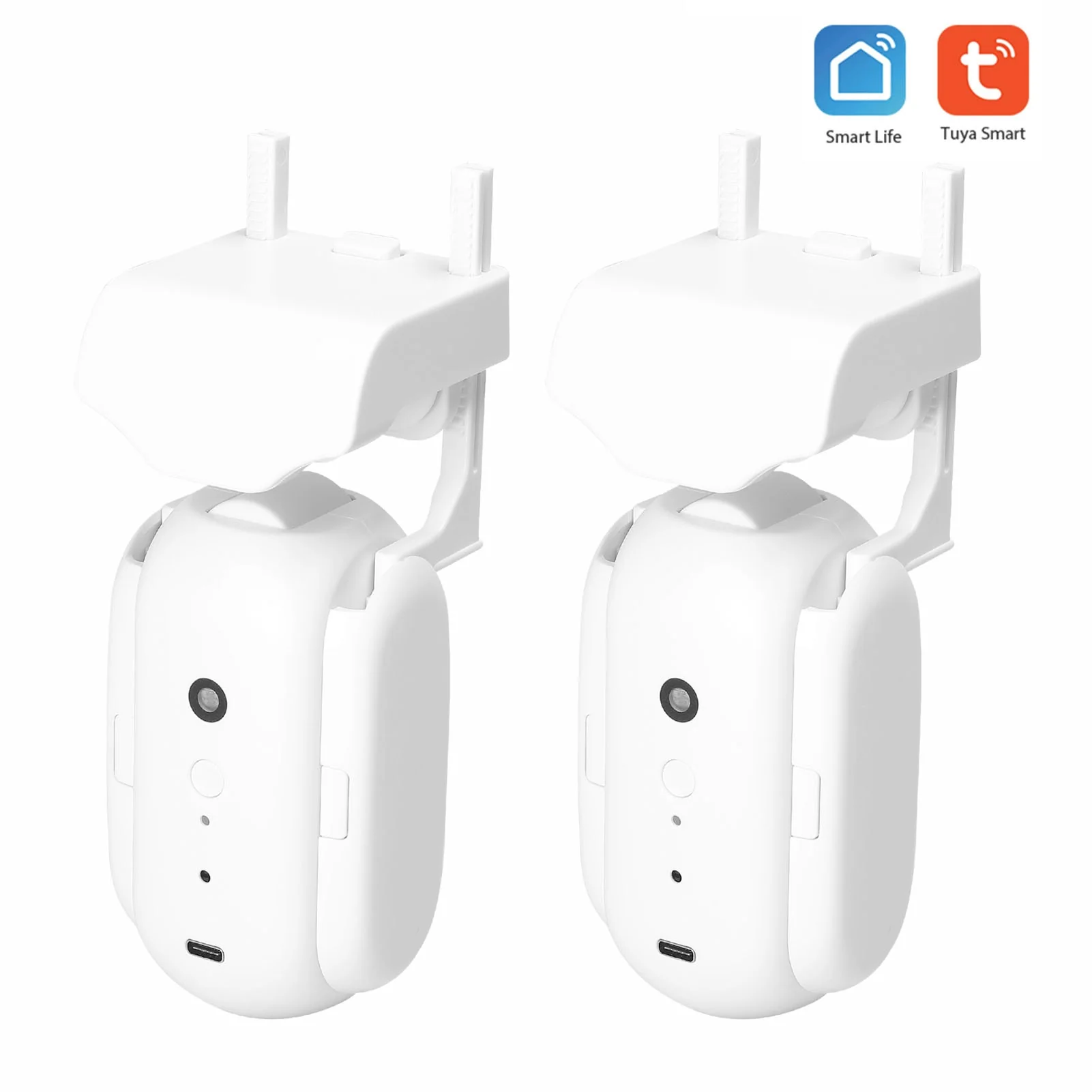
Official marketing photo
How well the robot performs will depend on how well the little white wheel is held against the bottom of the curtain rod. The arms that the upper sled attaches to are spring loaded for additional clamping force.
The case seems to be fairly generic and used across multiple brands so it’s safe to say that depending on the version / hardware variant, you may or may not have all of the featured inputs/sensors.
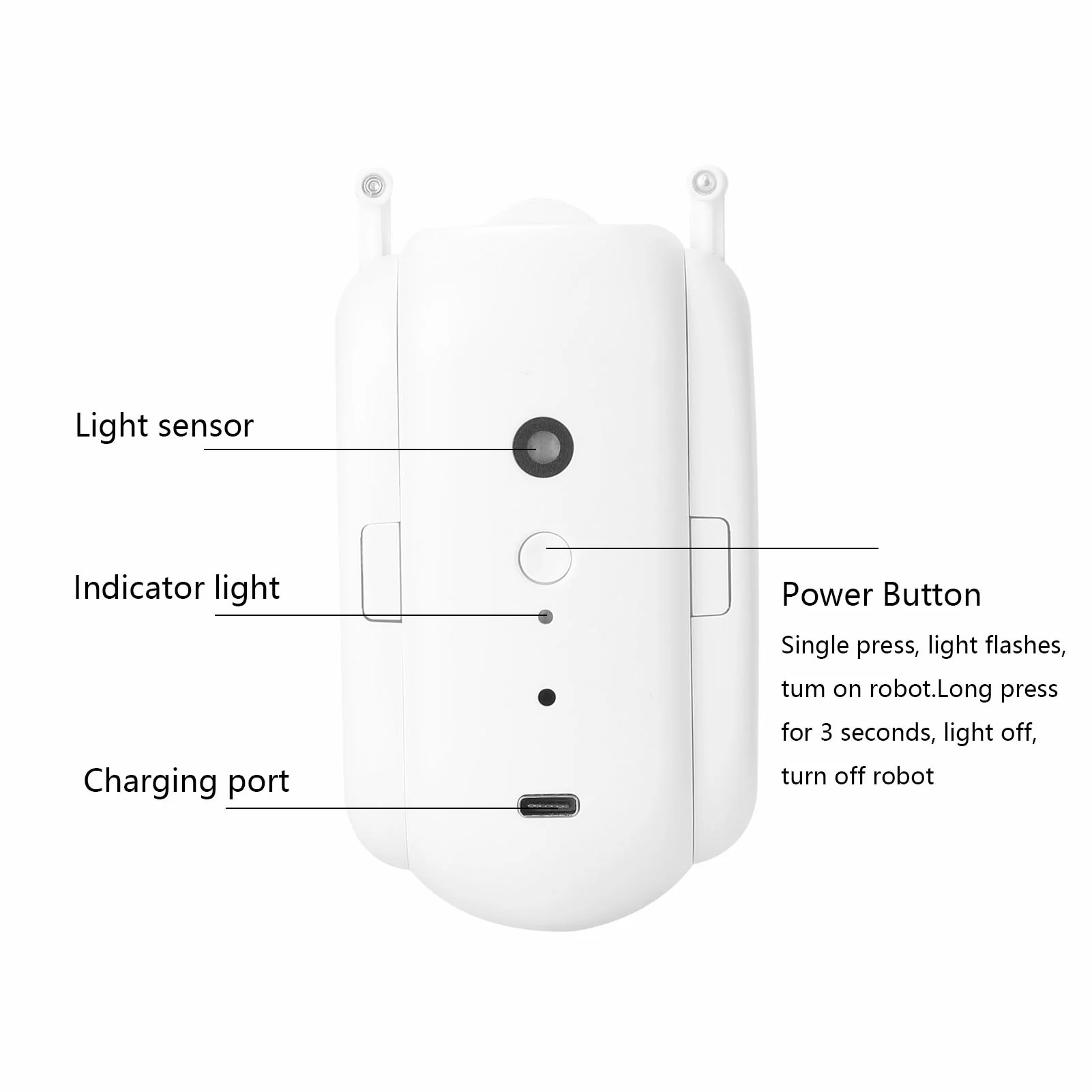
Only one of the two units in a pair comes equipped with the light sensor.
The light sensor is a nice touch. I will absolutely be borrowing that idea when designing my own solution 💡🤔!
Teardown
I’m not a huge fan of unboxing videos. The box is rather unremarkable; it sustained some damage in transit, but that’s what it’s supposed to do.
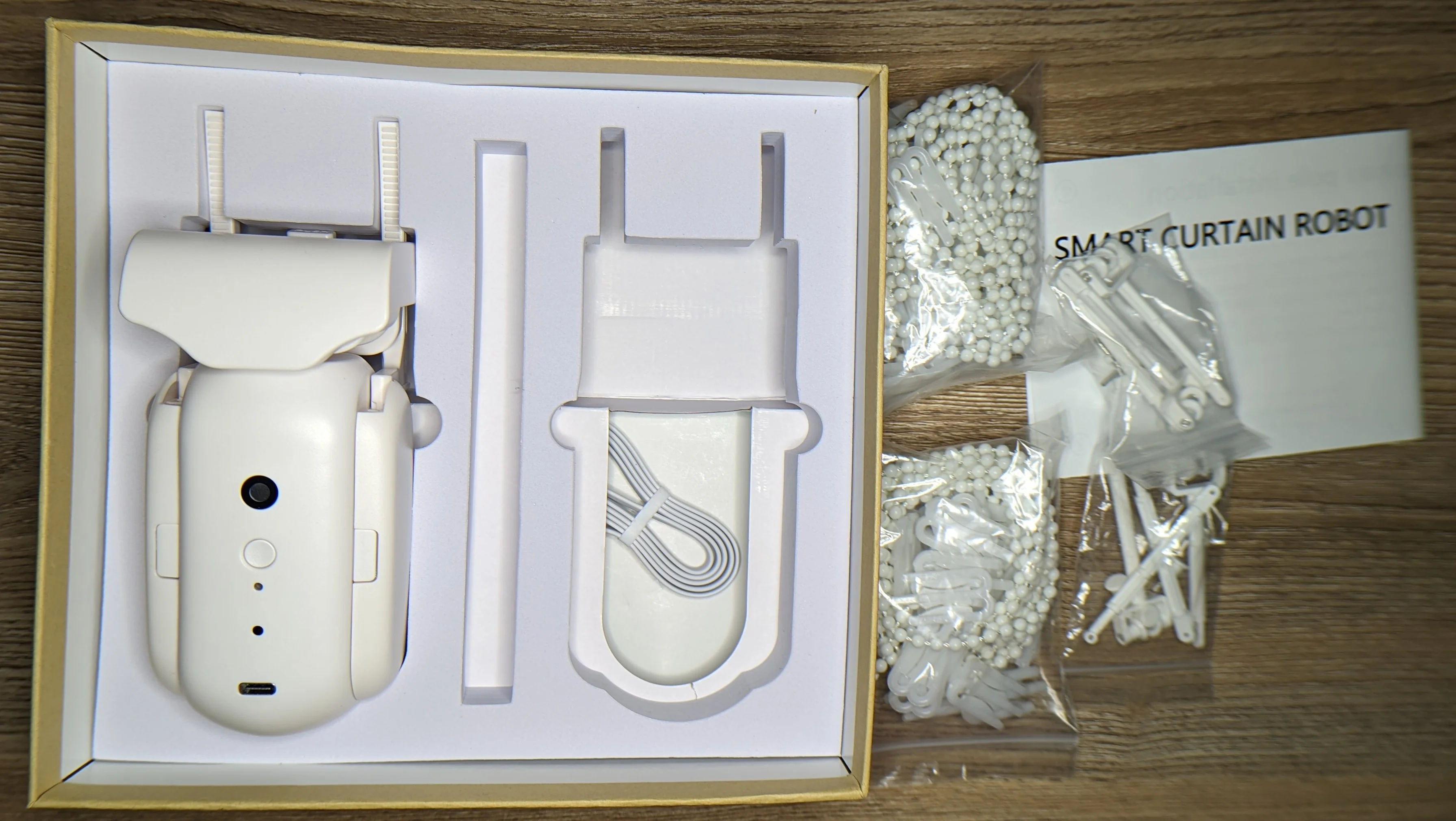
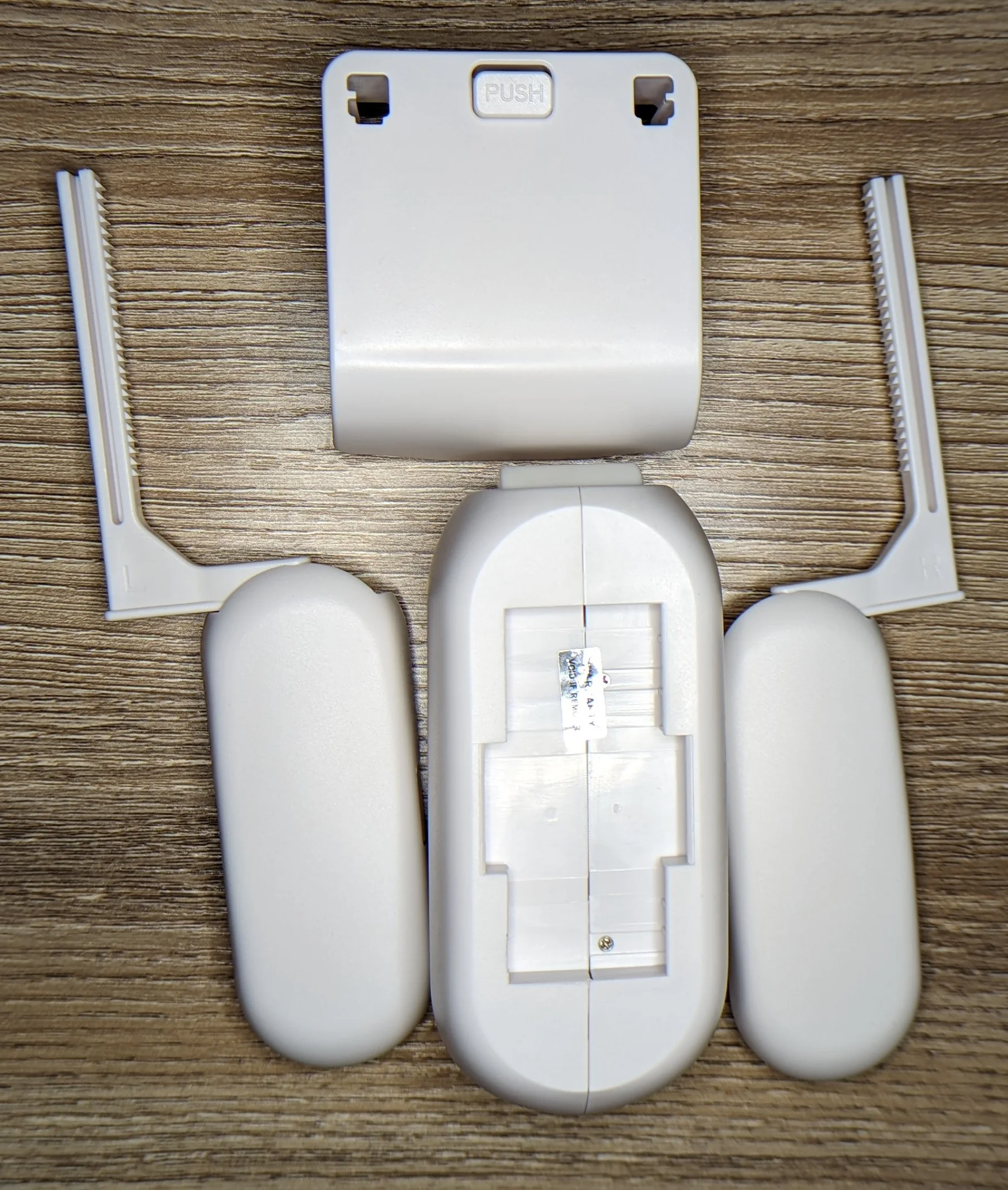
Relatively well packaged. The seller that I purchased from had explicit listings for different curtain rod styles so I am not sure why I received hardware for all styles. There does not appear to be any easy way to install this hardware.
The upper sled is coupled to the main body through two spring-loaded arms with a ratchet and paw setup. The arms can be easily removed from the main body if needed.
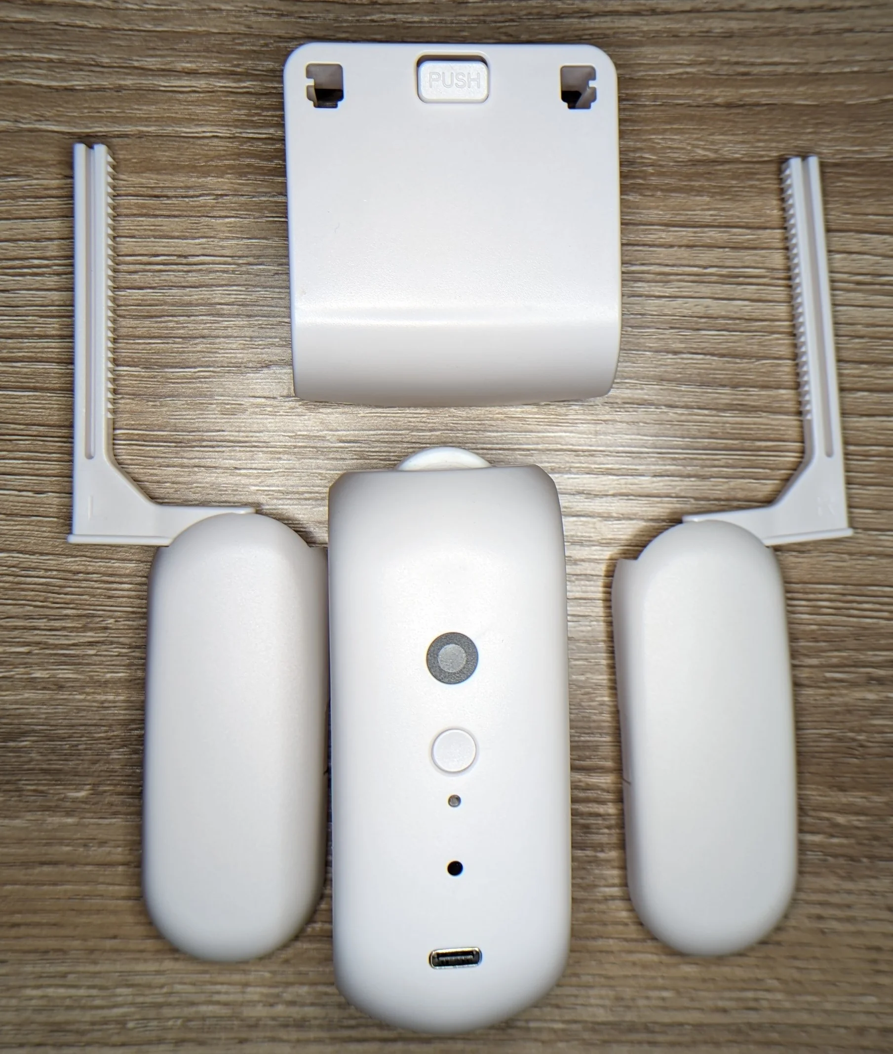
I am getting some vague Portal2 Turret vibes...
Since the entire weight of the robot will be hanging from the upper sled, the springs are the only thing that will pull the actuator wheel into the curtain rod. I don’t know how the springs will last over time, but I absolutely can foresee needing to re-tension things as the springs inevitably stretch out.

The ratchet/paws seem to indicate compatibility with some comically large diameter curtain rods!
Obligatory 'i void warranties' reference.
Use a Philips style J00 or J000 screwdriver to remove the four screws holding the thing together. Use any flat pry tool to crack the two halves apart.
Screw hiding under warranty void sticker and obvious mechanical/snap seam make it pretty obvious how this will come apart.
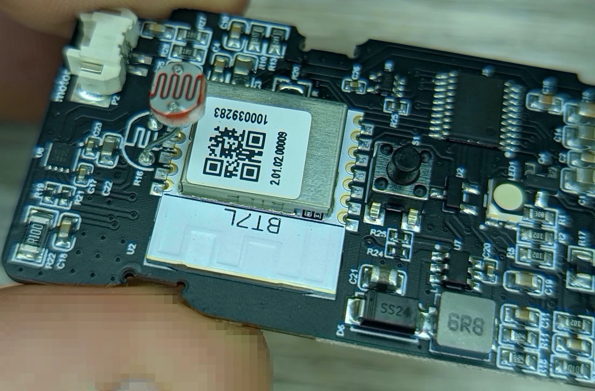
And with that, our first real look at the electronics inside!
I expected a simple PCB that contained a charge controller circuit for the battery and a simple motor driver with over current protection… and nothing else. I was sure that everything else would be handled directly by a the radio-on-module.
I absolutely did not expect the PCB to have provisions for … two radio modules!
A few other quick observations:
- The unpopulated radio module footprint does not match any ESP-8266 modules that I am familiar with.
- The populated radio module does look like a common ESP-12E module footprint… but the module is clearly not an ESP.
- The markings have been erased from all the interesting ICs 🤬.
- The 20 pin chip closest to the unpopulated module footprint could be anything but is likely the ‘housekeeping’ CPU. The populated radio module likely communicates with this chip to command the motor and check the sensors
- The product marketing photos indicated that there would be a light sensor. The PCB appears to have a foot print for an LDR… but it’s not populated… only a few passive components besides some radio-on-module
- The USB-C port does not have any active electronics connected to it. The port likely does not speak any power delivery protocols and certainly does not have a hidden UART for talking to either of the microcontrollers.
- No motor is visible so that means that it must be embedded in the comically small drive wheel…
Some more technical details are discussed below.
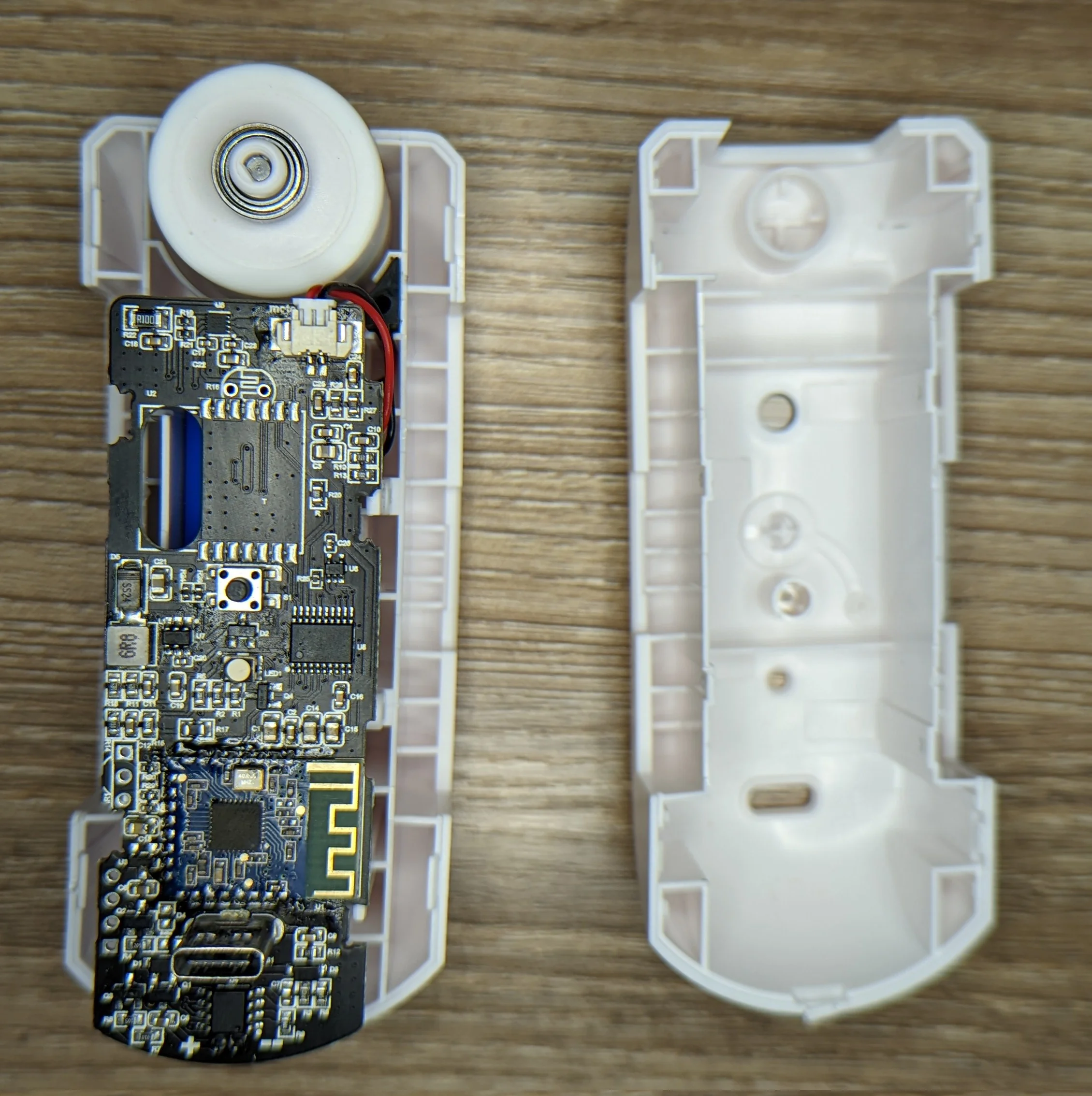
Huh. Was not expecting the PCB to be quite so big or complex!
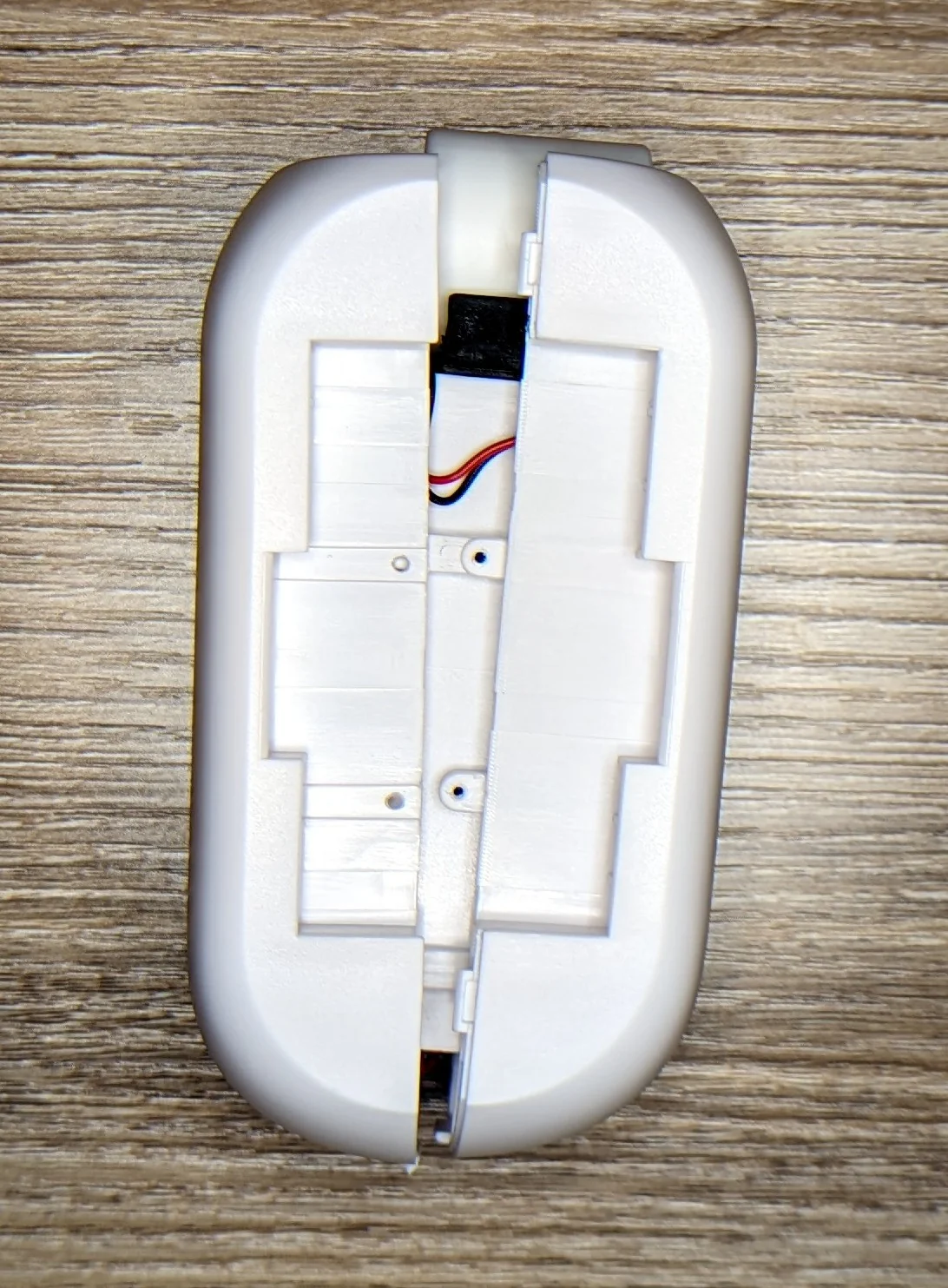
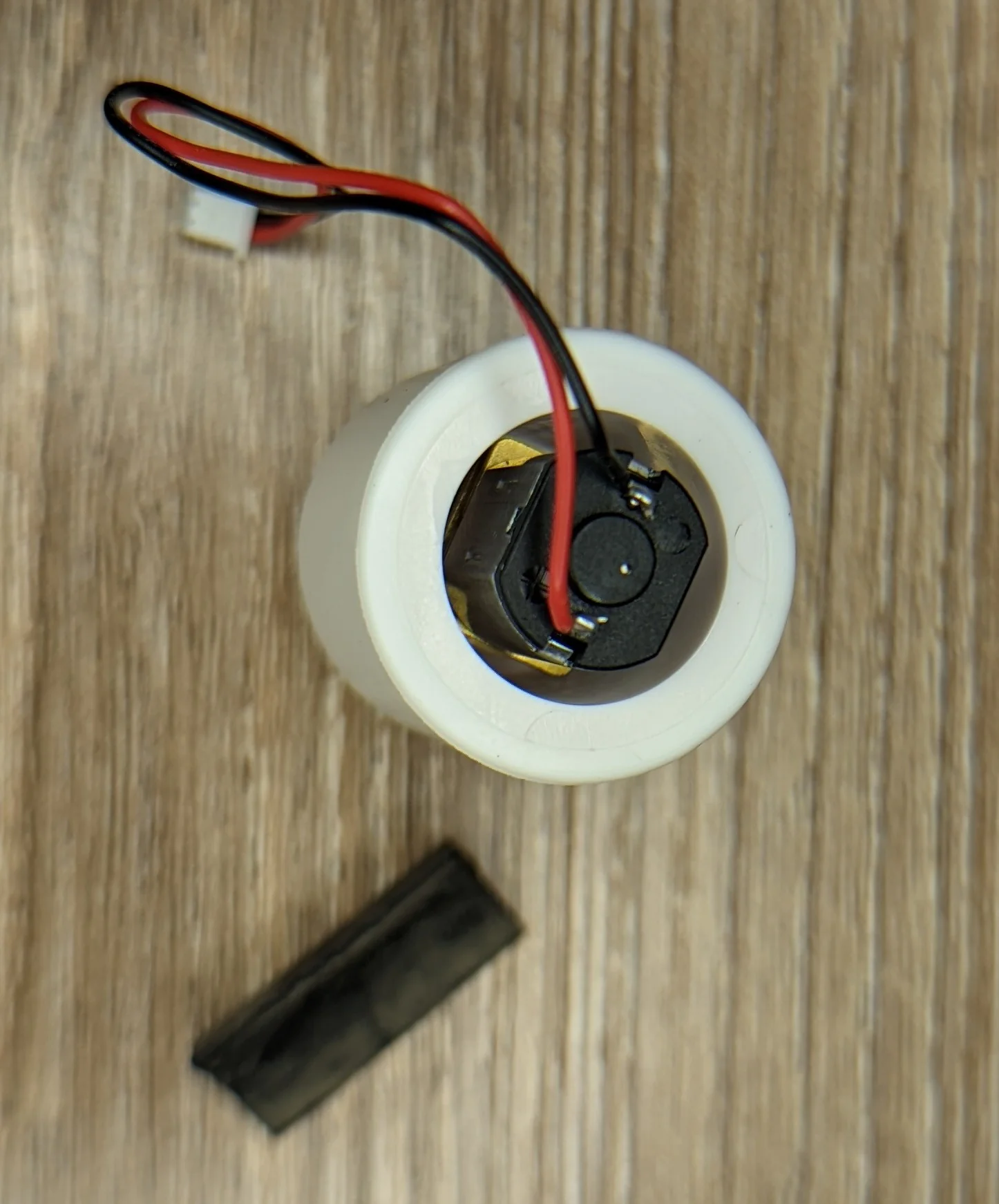
Lifting up the PCB reveals the battery pack. I did not slice the pack open to see which brand of cells went into the pack. Grateful that they didn't solder the battery directly to the PCB.
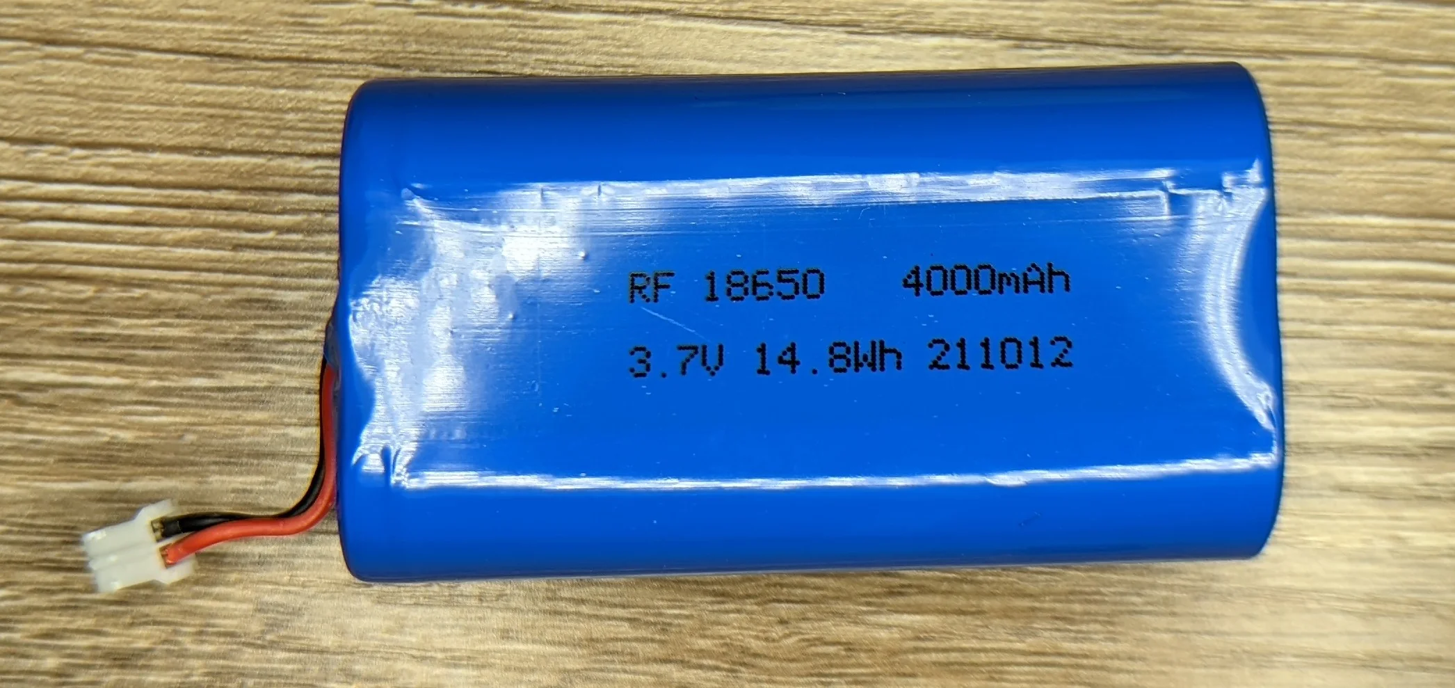
I have not tested the battery to see accurate the labeled capacity is.
I was still looking for that elusive light sensor so I opened up the second unit… and found it!
Other than the populated second radio module, R20 and the LDR, the PCBs appear identical.
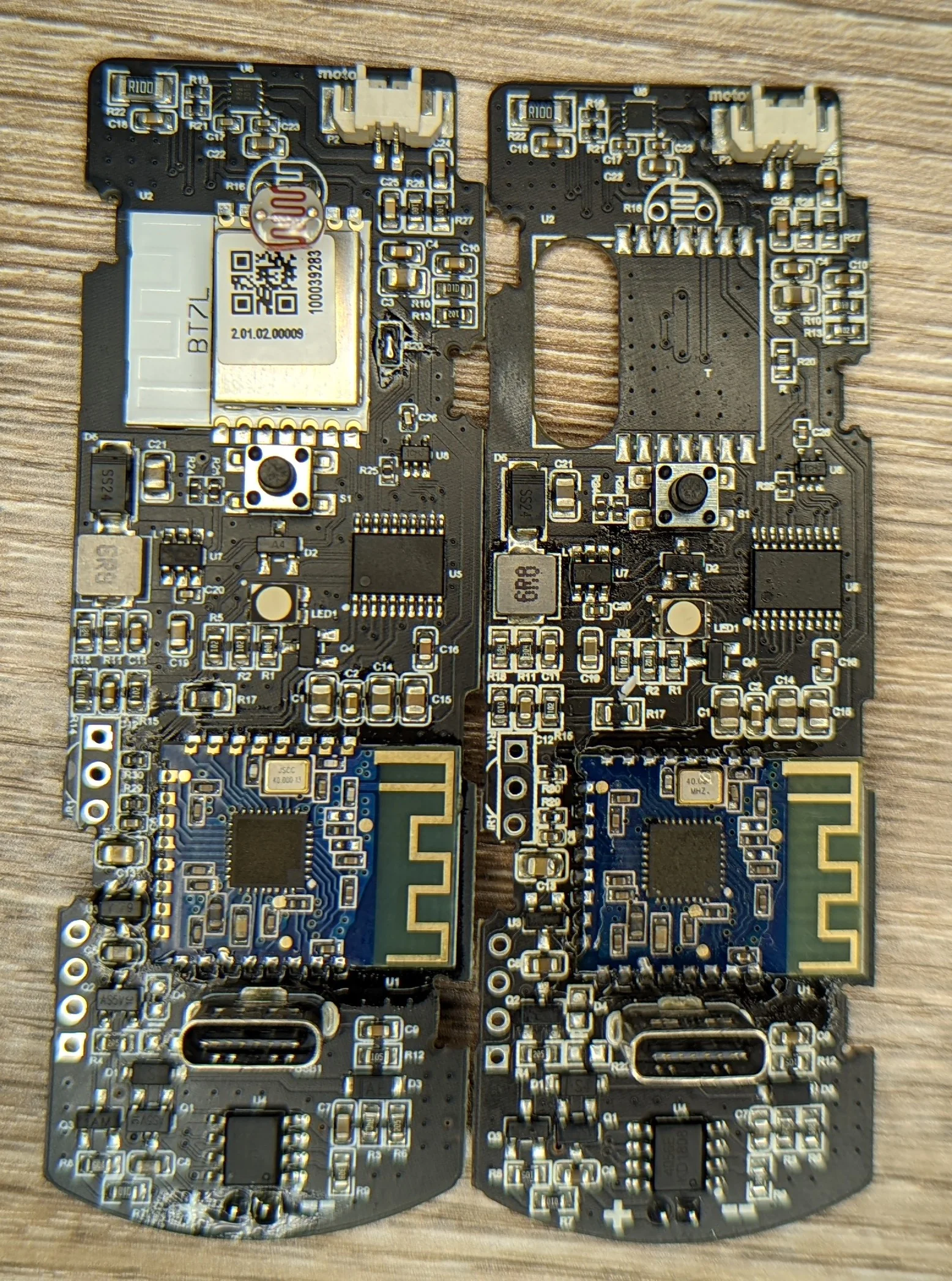
Something tells me that the PCB with two radio modules is the 'leader' out of the two.
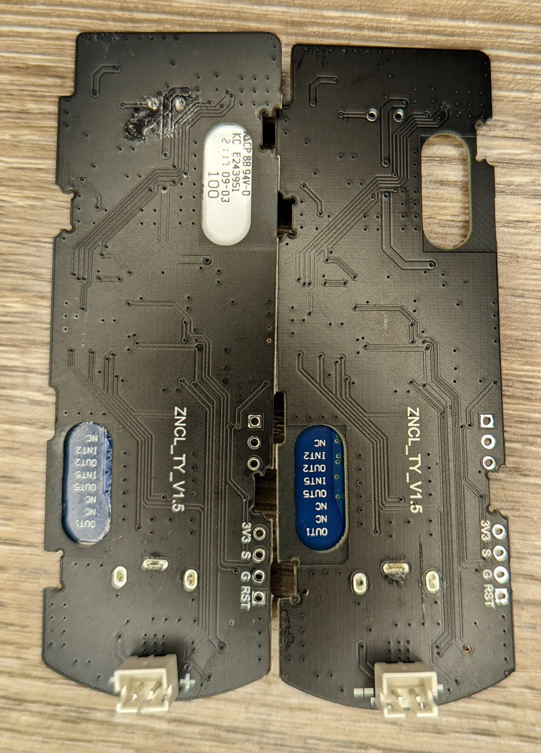
On the rear we can see an obvious programming / debug port and a PCB/product designator: ZNCL_TY_V1.5.
Giving that a quick google returns almost nothing. I did find this post from /u/coned_miro asking about a very similar PCB revision:
…The main board says ‘ZNCL_TY_V1.3’ on the back
Nothing new to be learned about the tuya device from that thread, sadly.
No, I didn't hook a scope up or trace out the obvious programming/debug header.
The App
I never intended to use the manufacturer provided app for anything other than the initial setup so this will be a very brief section. The robot was quickly discovered and provisioned through the app.
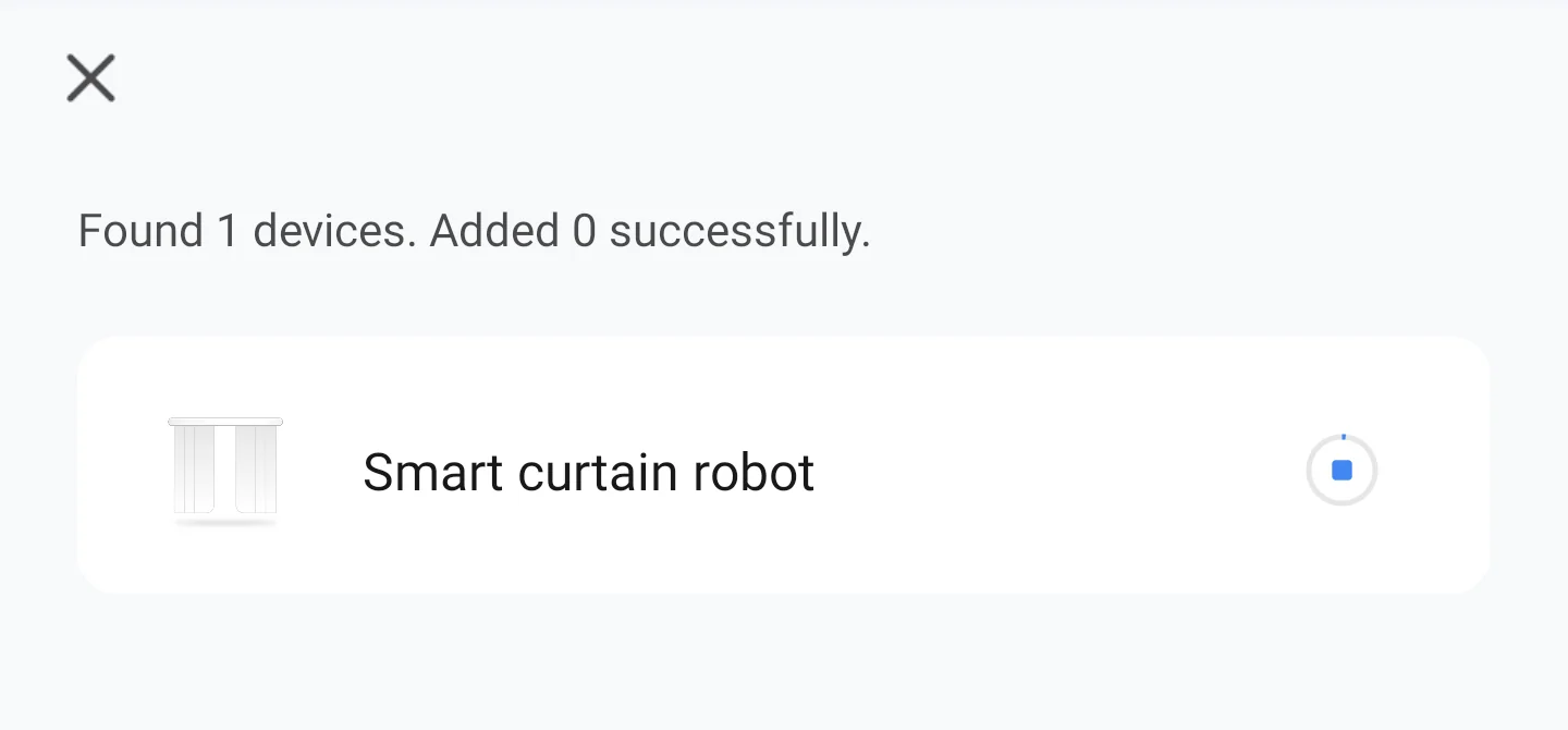
BTLE Pair/Provisioning was straightforward
The device calibration process is pretty rudimentary and does not have an easy “undo” process.
If you make a mistake in configuring the direction/distance that the robot needs to travel for curtain open/close, you have to factory reset the device. Fortunately this is easy to do in app and discovering/re-provisioning the device takes only a few seconds.
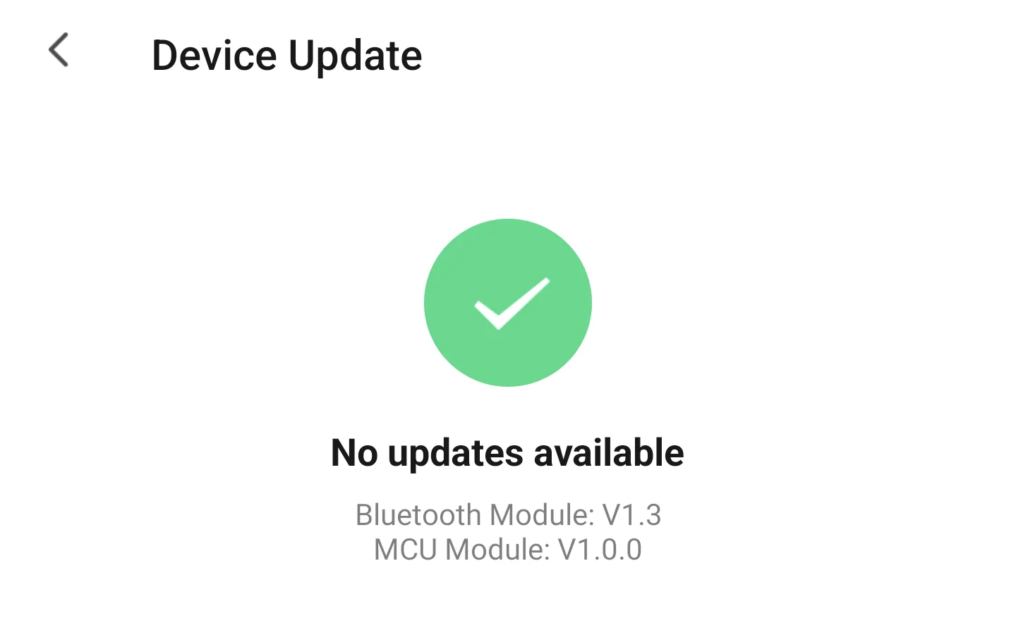
The two firmware version strings strongly hints at a “two processors for two domains” architecture: the anonymous 20pin chip runs everything on the PCB and the BT7L module deals with external communications and is only abstractly aware of the PCB/motor/sensor/battery state.
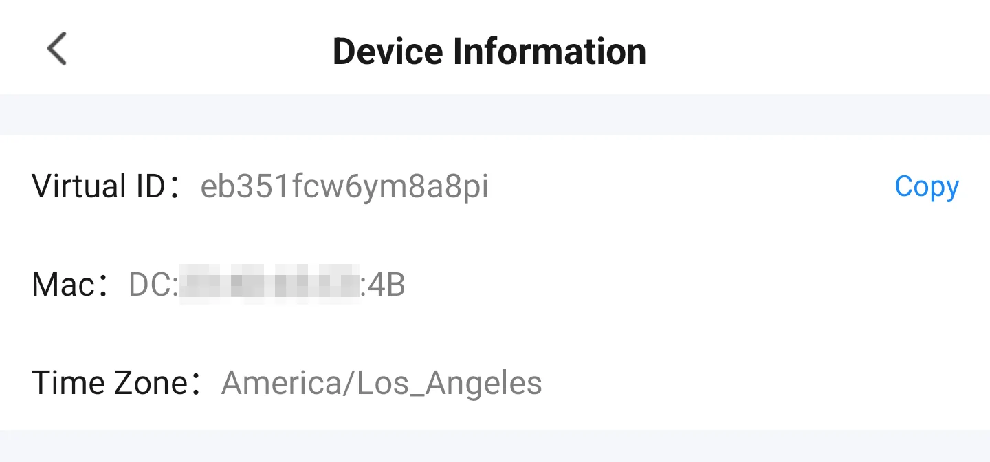
I have only skimmed the TuYa developer documentation but I think that the VirtualID is common to _all_ of the curtain robots.
Verdict
While disappointing that there was no easily hackable ESP microcontroller running the show, it doesn’t matter. I can’t use this product as is for my intended application; the motor is just too puny for the task.
The brains(?)
My curtains are rather thick and heavy. A tiny motor can’t possibly have enough power to do this on it’s own… especially with a sub-optimal coupling mechanism!
To give the motor a fighting chance, the engineers went with a TON of reduction-gearing. The gearbox allows a wimpy but fast motor to become a more grunty motor at the expense of speed. Almost anything small that rotates at high speed will come with some unpleasant sounds. This is ESPECIALLY true for cheaply made gearbox full of small gears.
This means that any invocation of the robot will be noisy. You can expect the noisy little device to slowly move across the curtain rod. 🙄
The robot struggled to push the curtains together towards the end of an opening cycle… it would often skip in place as the drive wheel struggled to keep enough traction on the curtin rod.
Likewise, asking the robot to pull the bucked up curtains closed was out of the question without some sort of an assist.
Because the robot has no fixed position sensor, it can’t really measure where on the curtain rod it is. Every time the drive wheel skips, the difference between where the robot thinks it is and where it actually is will grow.
If you can stand the whiny/slow movement, expect frequent re-calibrations 👎.
TL;DR: Looks like there’s a reason why the hobbyist/DIY community has produced such a wide variety of bespoke curtain/drape actuators… most of the commercial ones have sacrificed too much in order to be widely usable. The solution that I end up implementing will be designed with my heavy drapes in mind and will use an appropriately sized and quiet motor!
A simple brushed DC motor with no position encoder and what is probably a cheaply made gearbox. What could go wrong?
Technical Details
A highly condensed version of my initial notes from setup/teardown:
Was not expecting multiple radio units. The blue radio-module that both PCBs have in common appears to be a
JDY-25M.There is a SDK for the
JDY-25Mavailable here. It contains some english documentation.The
JDY-25MSDK does not appear to contain any information about how to program the chip or build a custom firmware. You are meant to interface with the ‘stock’ firmware viaAT+commands. The firmware appears to support multiple modes… including a bi-directional communication link. I suspect that the unique radio module is the connection to the outside world and the the two identical radio modules are used to coordinate movement between the two podsI was never able to get the ‘follower’ unit to pair or otherwise command the second unit.
The unique radio module is a module made specifically by/for TuYa: https://developer.tuya.com/en/docs/iot/bt7l?id=K96gqp1dp6iiw
PCB Markings
AKA SEO optimization 😉