Roborock S8 Pro Ultra Teardown
Roborock S8 teardown
I recently acquired the new S8 from Roborock to replace my rapidly failing roomba.
While I am patiently waiting for Dennis and Hypfer to add Valetudo support, I thought I’d have a peek inside to see if this model will be any more serviceable or maintainable than my current vacuum.
From what I’m told, the S7 and the S8 are supposed to be pretty similar so here’s to hoping that it’s not too much more of a wait.
In the mean time this post is going “live” with photos of the docking station internals and a few photos of the vacuum. I ran out of time to finish the S8 teardown but I’ll update this post when I have made progress. Assuming the S8 is similar to the S7, I imagine that the procedure and internals will be similar.
The dock
Fortunately, it’s pretty easy to open the huge charging station/dock up. Really, you just need a single philips screwdriver for the ~10 screws on the rear. There is one sticker covering a screw on the rear but it’s not the “tamper-evident” kind so it should be easy enough to replace if needed.
Excess cable slack can be looped around the rear of the docking station to minimize errant cords.
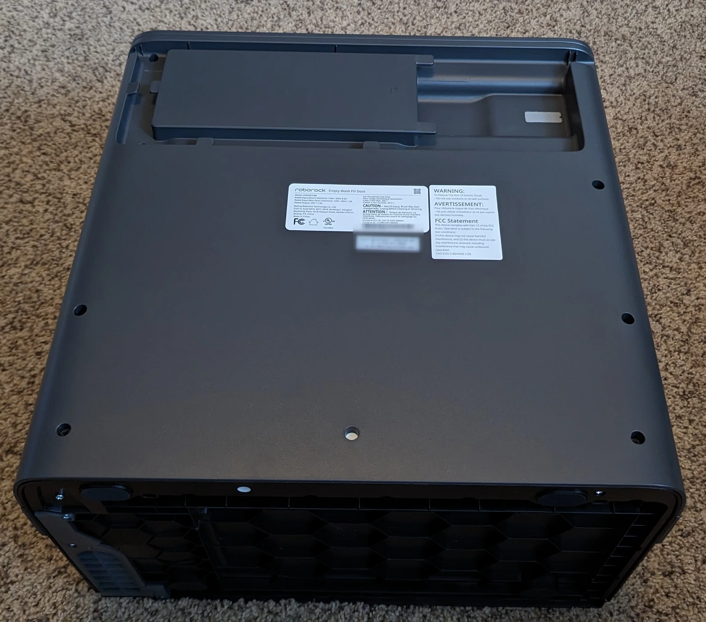
Note the white sticker covering the screw in the middle on the bottom.
Near the mains input is a simple USB-C port.
dmesg doesn’t show any signs of life on the port both with and without the mains cable plugged in. I have not yet tried with the robot docked so there may be some simple handshake that’s needed before this port becomes interesting.

With screws removed, the rear panel lifts off to reveal the internals. The overall layout seems logical and there’s lots of room between components which is nice to see. Each component is well labeled secured to the main body with standard screws and Zip-Ties.
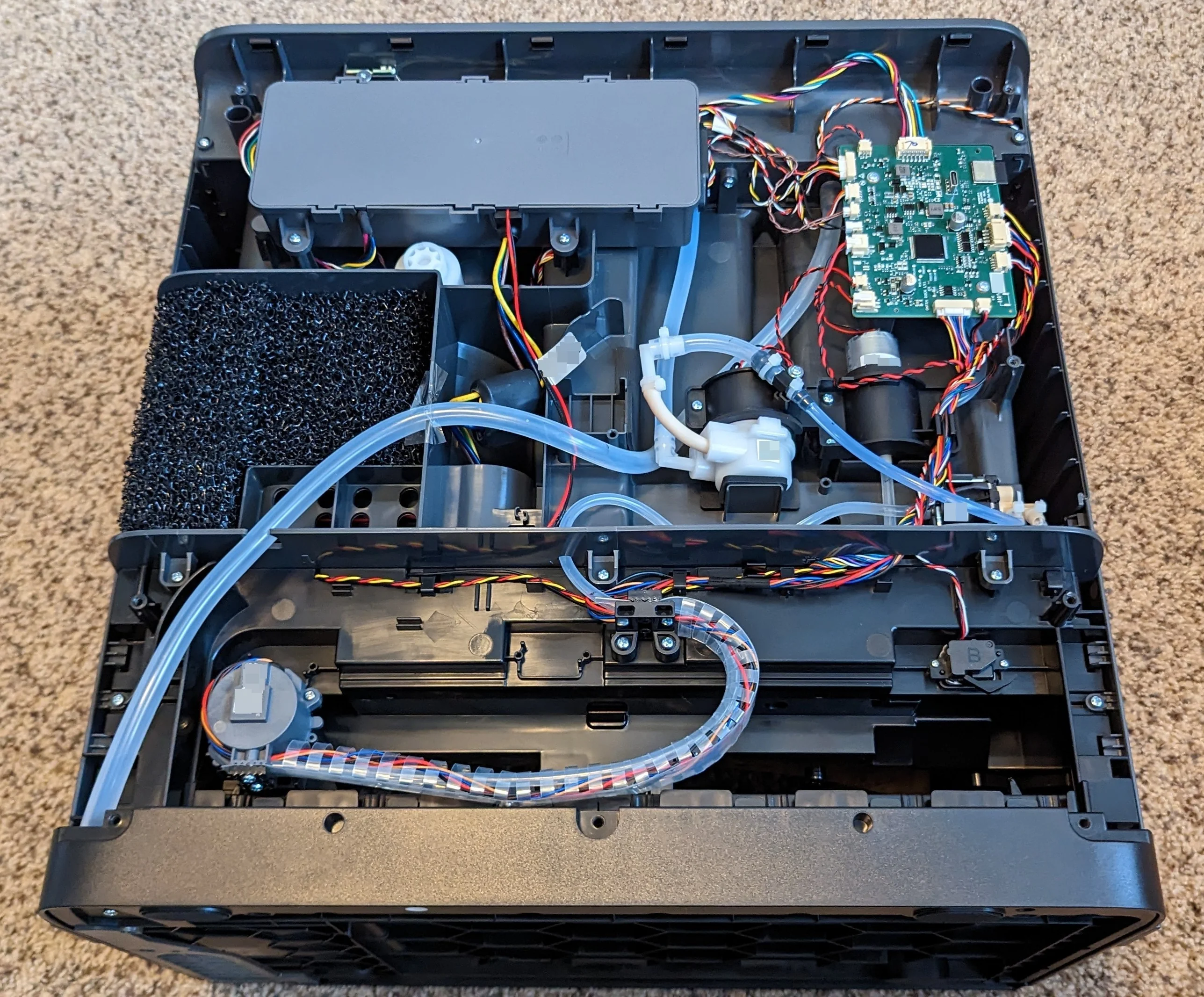
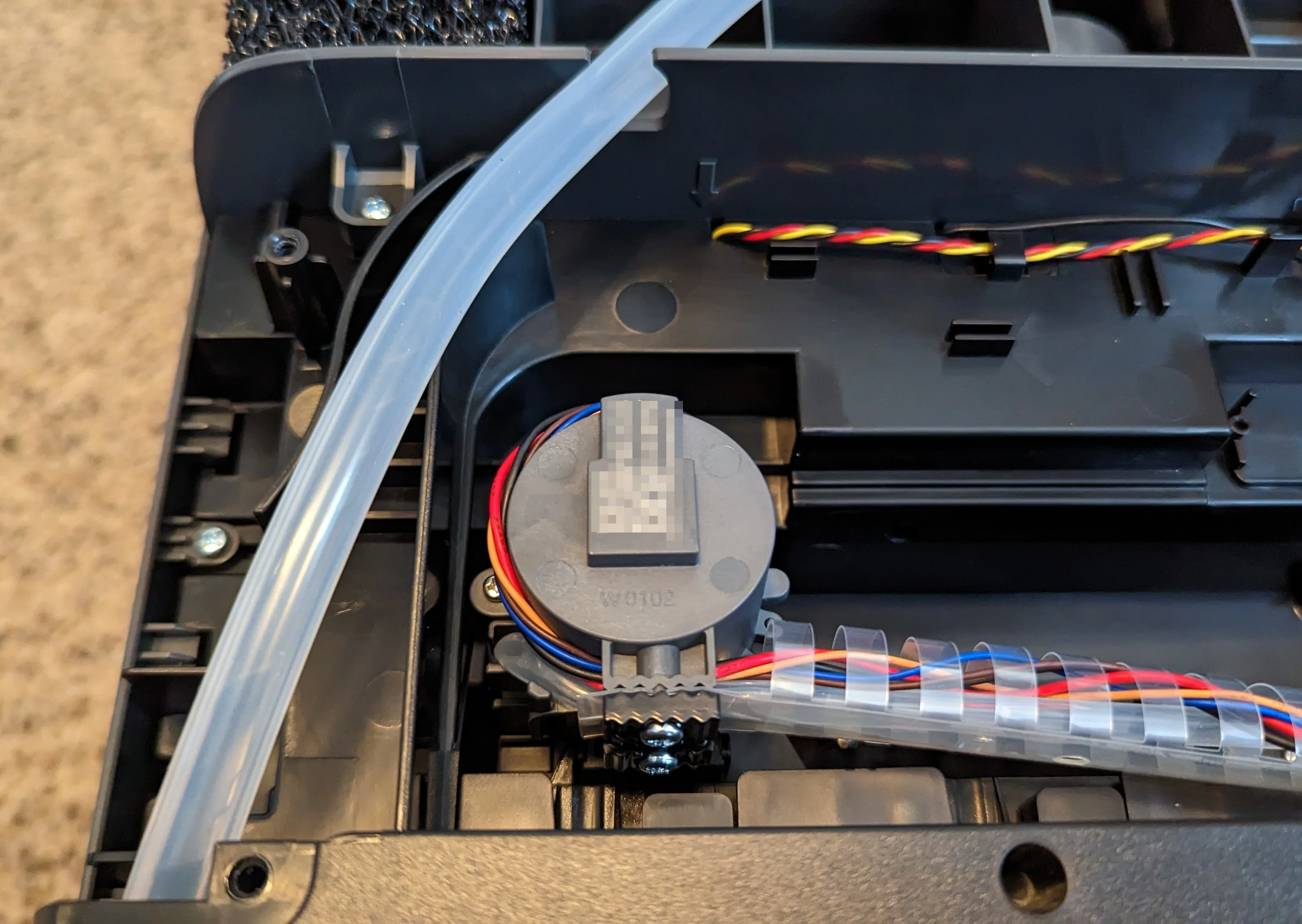
In addition to the small features molded into the body for cable management, the cables to the components that move are protected with an easy to remove cable chain.

The strong vaccuum motor that empties the mobile dustbin into the larger bin is powered directly via mains but isn’t easily accessible.
The mains PSU is nothing special to write home about. There is a low-voltage connection right next to the mains cabling that heads down to the main “evacuation” suction motor but there is no obvious relay.

Here’s a closeup of the main control board for the docking station.
Each of the connectors around the edge is a different size/number of pins os it’s virtually impossible to plug the wrong cable in to the wrong port - nice!
The conformal coating does obscure component IDs and traces, but you can still get a high-level idea of the topology. More than likely, all sensors and actuators are controlled by the Nation N32G455 and the ESP32 is (probably) just there for communicating status to the robot and/or cloud.

From this angle it’s a bit easier to see where the USB-C traces go but since the ESP32 module is BGA packaged and everything is conformally coated, I skipped the tedious work of trying to beep things out.
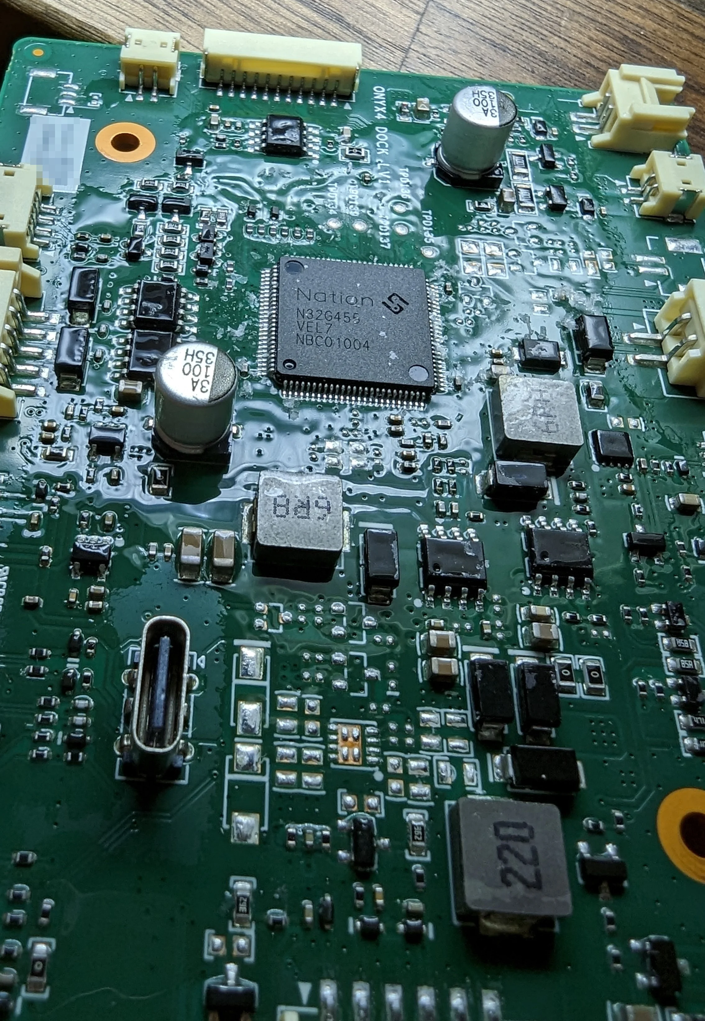
At least the conformal coating is pretty easy to rub off the IC.
The vacuum
More photos coming in a later update, but here’s what I have so far.
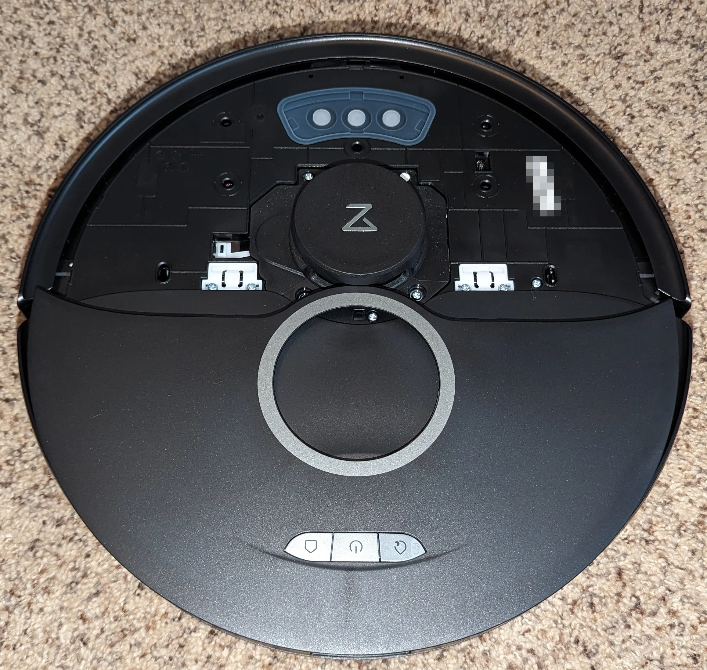
It would be better if Roborock provided tools to verify this claim, but at least they're trying to address consumer privacy concerns. Like with the S7, the panel surrounding the LIDAR puck can be pried off.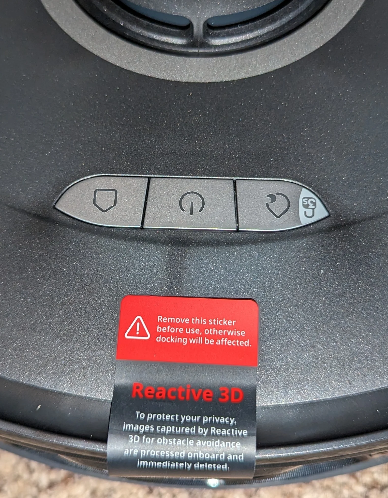
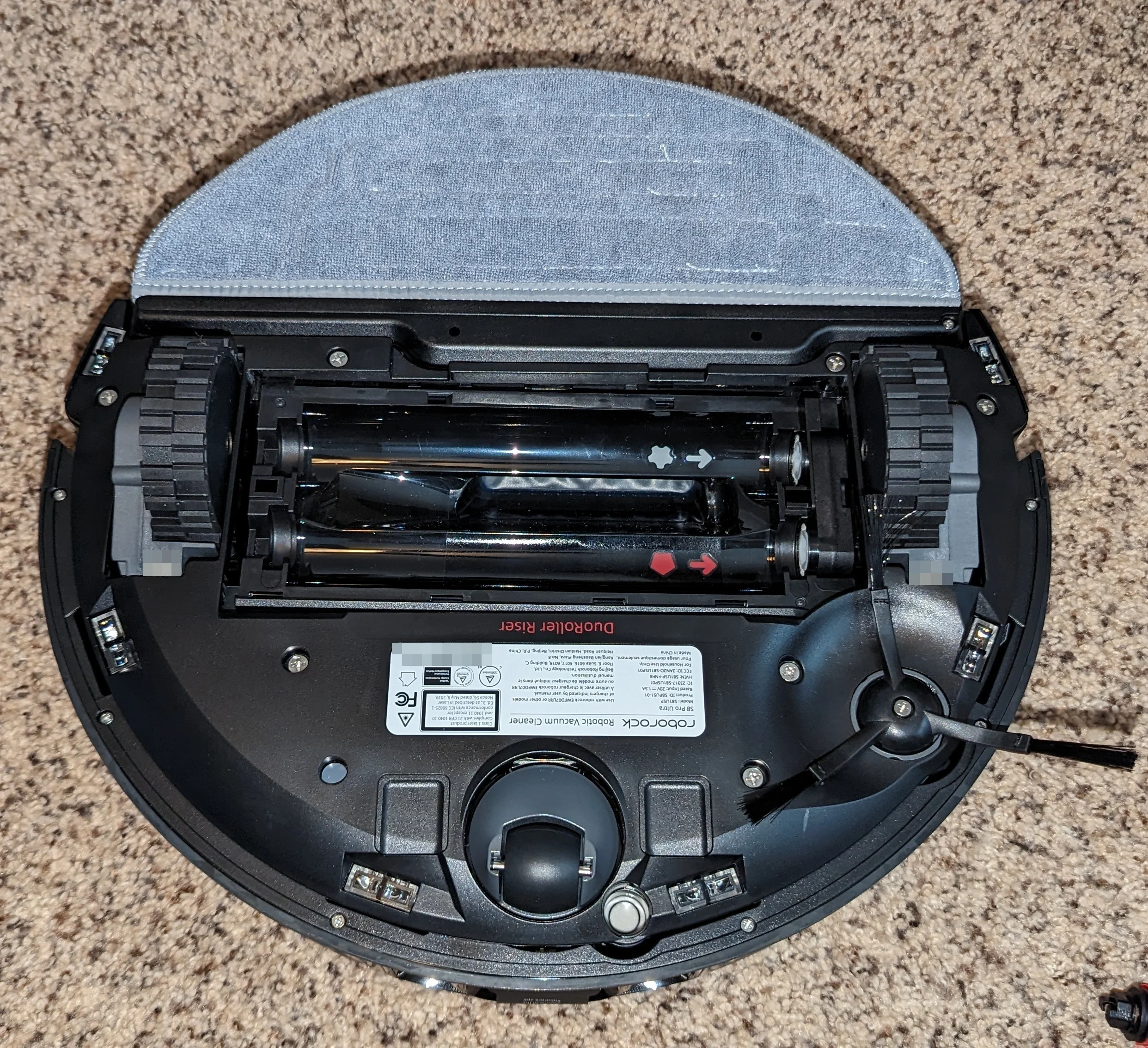
Nice to see that the labeling for which roller goes into which position is molding into the robot body for ultimate wear-resistance.
And here’s a shot of the LIDAR pcb.

As for getting into the rest of the robot, it’s not that difficult. Standard “keep track of all the screws and take photos at each step” advice applies here.
You can follow the the existing S7 teardown guides for the initial steps but once you remove the front bumper just look for screws that hold the top lid onto the body of the robot. There are two obvious ones, two next to the castor wheel and a few more hiding under the mop pad. With those removed, the lid slides off pretty easily to reveal the PCB:
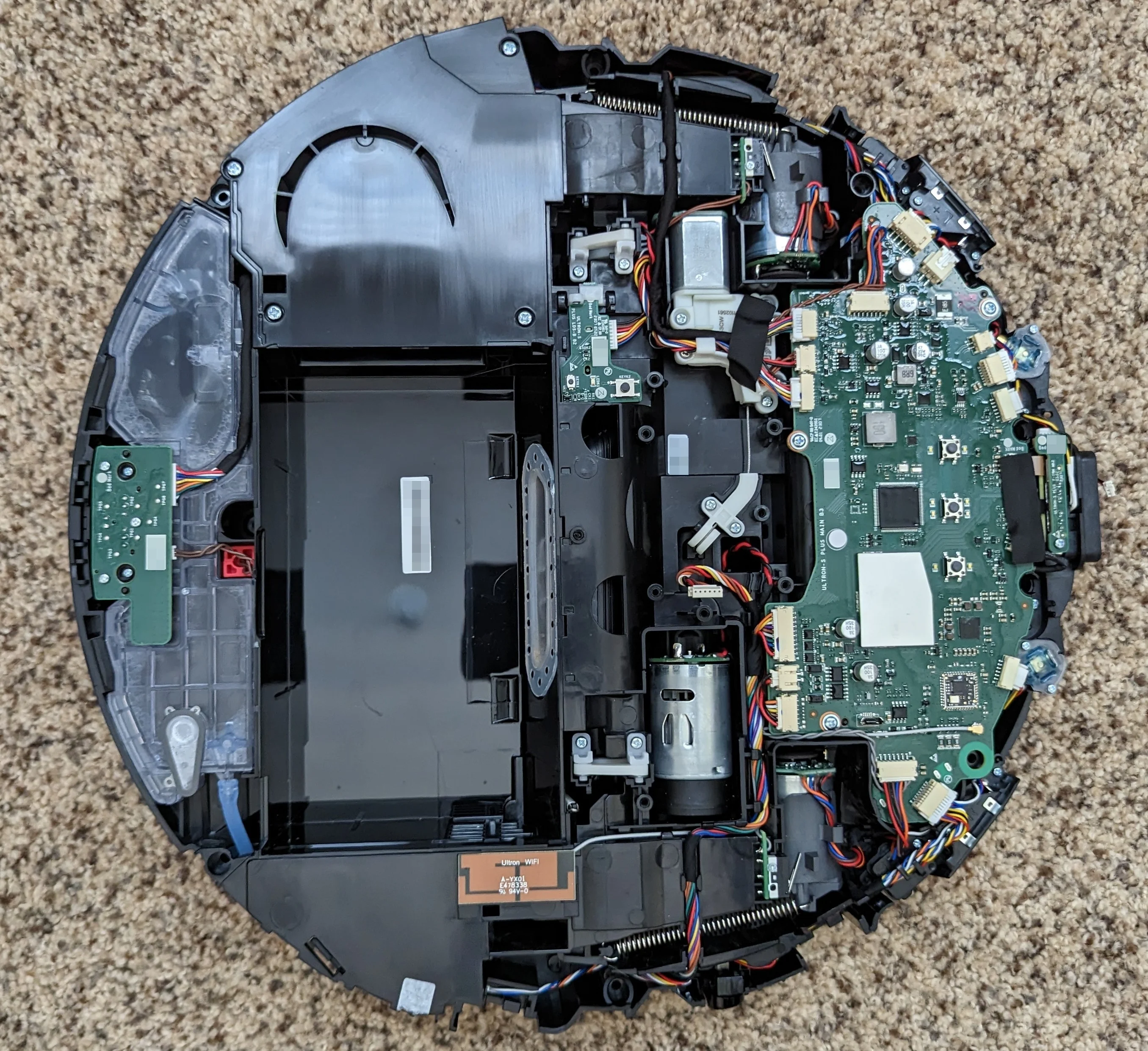
There’s a few interesting things to note here:
The roller brush assembly and mop head are lifted up via small steel cables. You can see the actuator motor for the main brush assembly just off of the top left corner of the PCB. The steel cable runs through the white plastic guides which route it around other internal components. The “space claim” portion of this design must have been pretty interesting :).
There are only two small locating features for the PCB. When installing the PCB back in to the chassis start with the small plastic peg between the screw and the micro USB port. If you seat this corner of the PCB first and everything else should fall into place nicely.
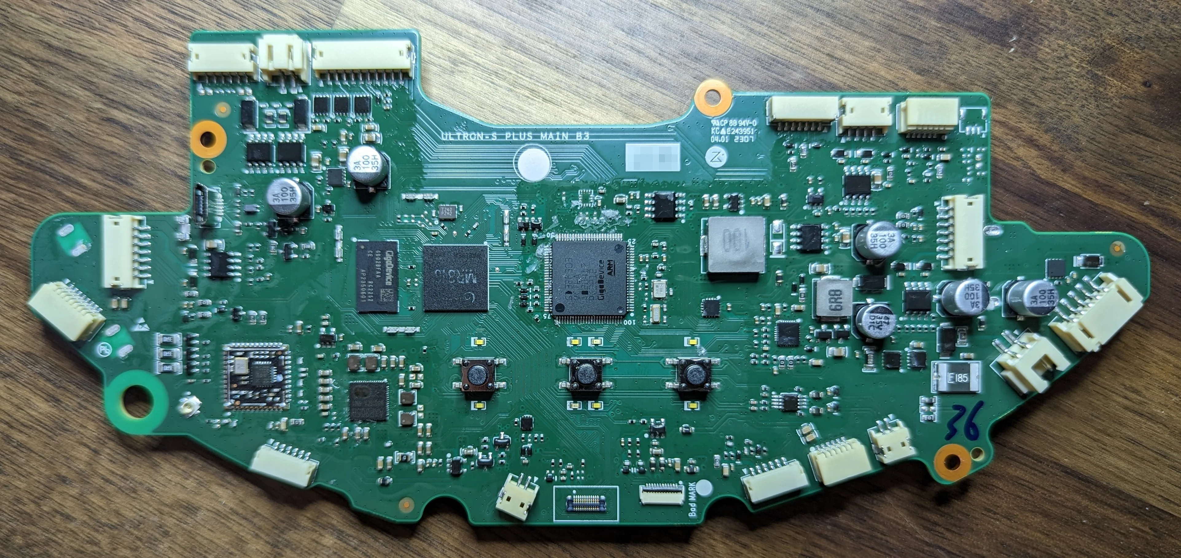
The conformal coating is annoying but here’s the big players:
An Allwinner
MR813runs the show.Samsung
KLM4G1for RAM.A GigaDevice
GDQ2BFAA-CE4Gb flash chip for OS storage.A
GDQ2BFAAhandles everything low level.WiFi provided by
RTL8189FTV.