Generic RGB Wall Switch teardown
Yep! Another teardown post! This one was also a cheap “because i’m curious” post.
What
It’s a ‘decora’ style wall switch with WiFI and an RGB color changing paddle.

The product listing was very non specific:
EU US WiFi Smart Wall Switch Push Button Timer Relay Switch Voice Remote Control RGB LED Night Light Lamp TUYA Alexa Google Home
I saw TuYa in the item description and hoped that it would be based on an ESP8266 module or at least use a pin-compatible module. After all, there are a few such devices on the Wall Switches and Dimmers section of the tasmota templates repository.
Teardown
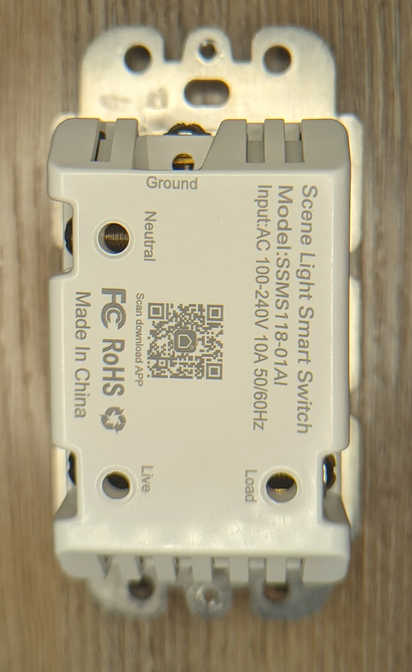
Almost immediately after opening it became clear: the item is a variant of the SSMS118-01AI switch.
Other than that, the internals are pretty predictable / standard.
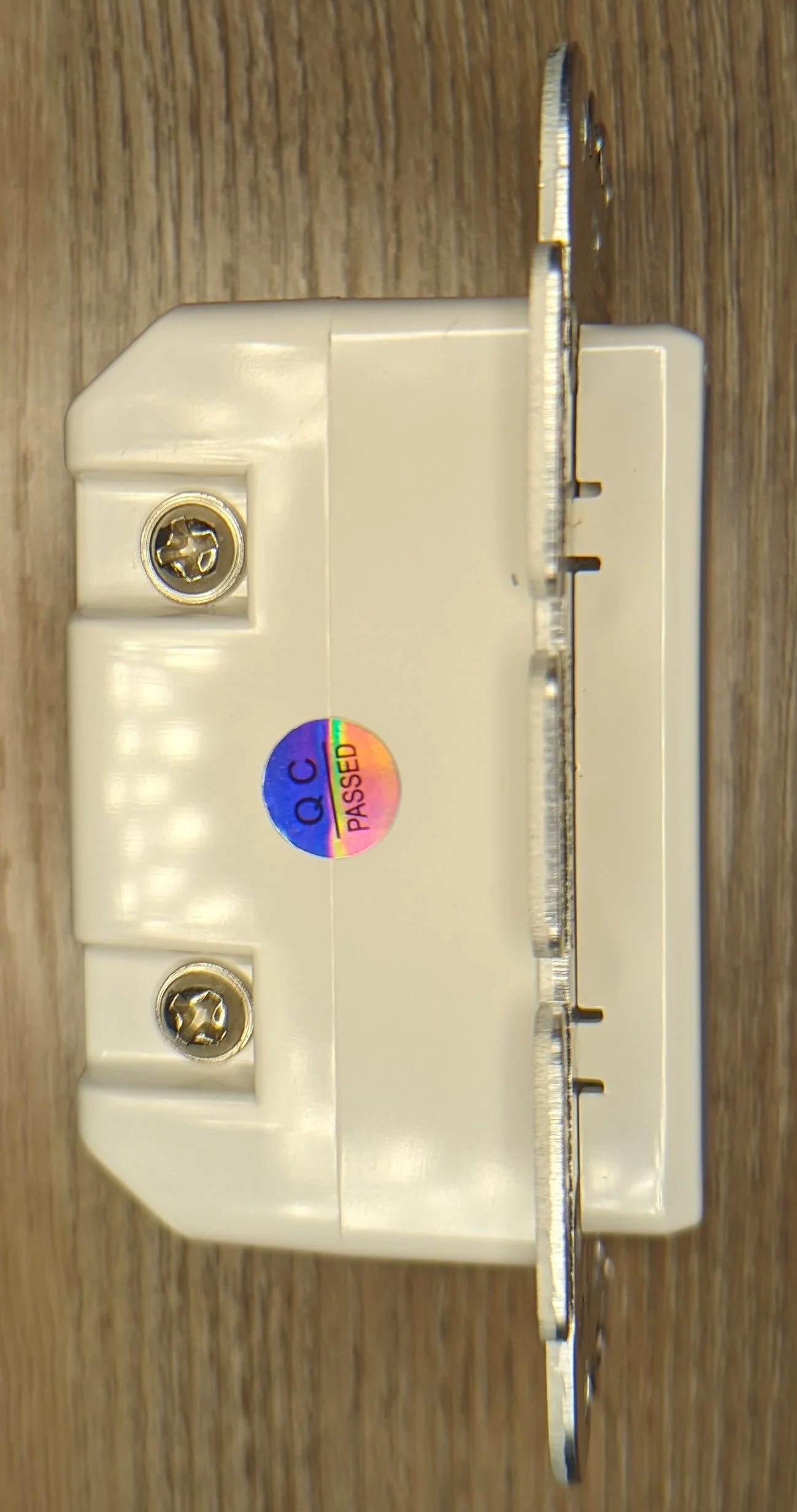
From the side you can see plastic clips holding the paddle to the Aluminum substrate.
No screws on the back, so we probably open it from the front.
Not sure about how code compliant those wire terminal/lugs are.
If the paddle was removed, the philips screws would be unobstructed.

RGB leds on a thin PCB with a reflective sticker attached. The sticker probably makes the LEDs appear brighter.

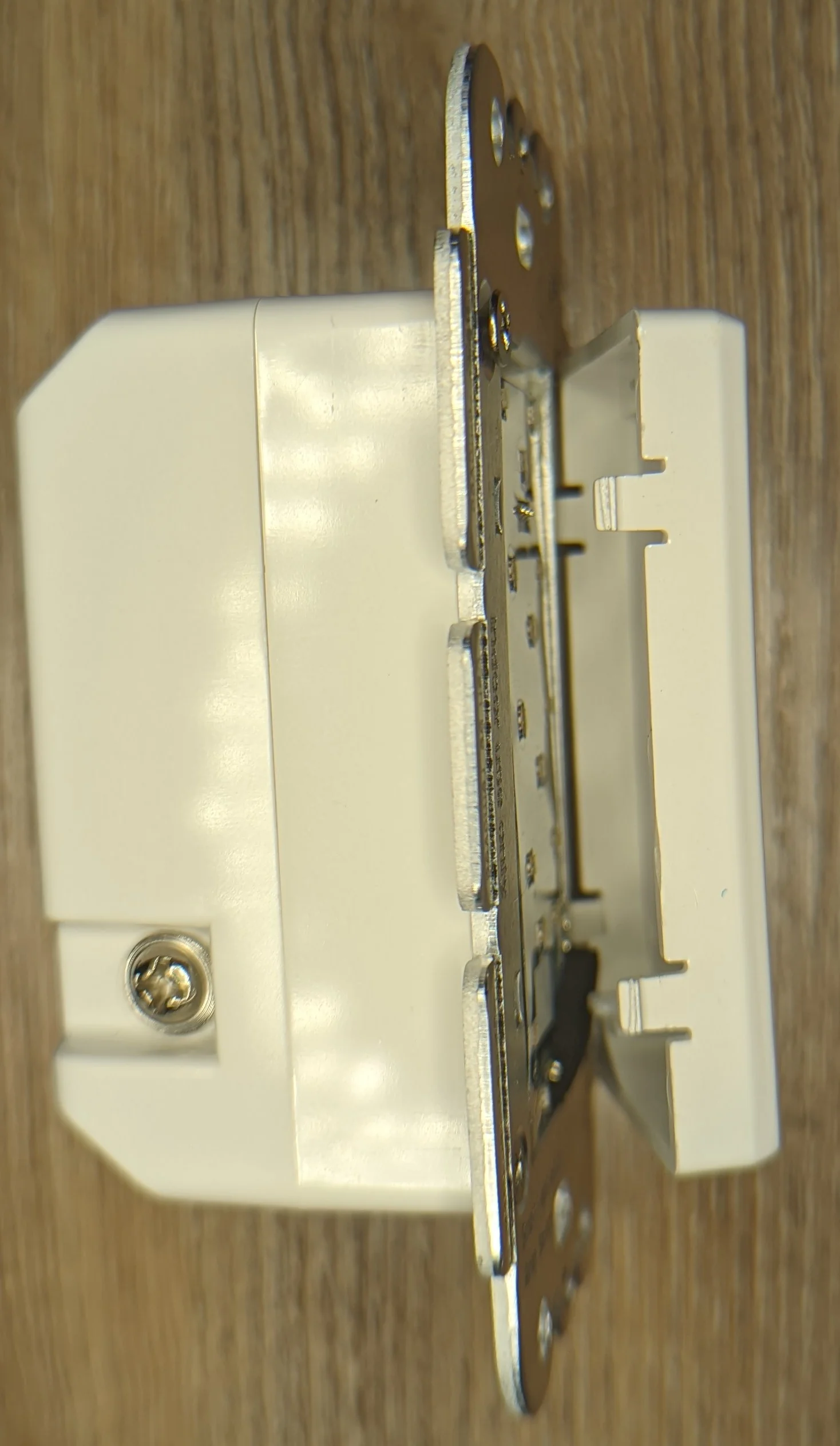
Philips screws removed and the switch immediately splits in half. I wish everything was this easy to get into!

Almost textbook design at this point; keep the mains voltage on it’s own PCB and only send back low voltage / signal to the controller PCB.
The mains PCB attaches to the controller PCB via 3 sets of three male/female pin headers along the top and bottom of the left edge and one side of the right edge.

Sparsely populated and a generic no-name relay. But at least there’s a fuse!

Mains PCB is marked HYS-00-004-MAIN_V1.1 with a datecode of 2019-5-7.
Equally sparse controller PCB. Aside from the massive mechanical switch and the three transistors for the RGB leds, everything lives on the ESP module. At first glance, the module looks like a standard ESP-12… but it isn’t! There are 6 pins on each of the three edges, not the 8 that would be present on an ESP-12 module.
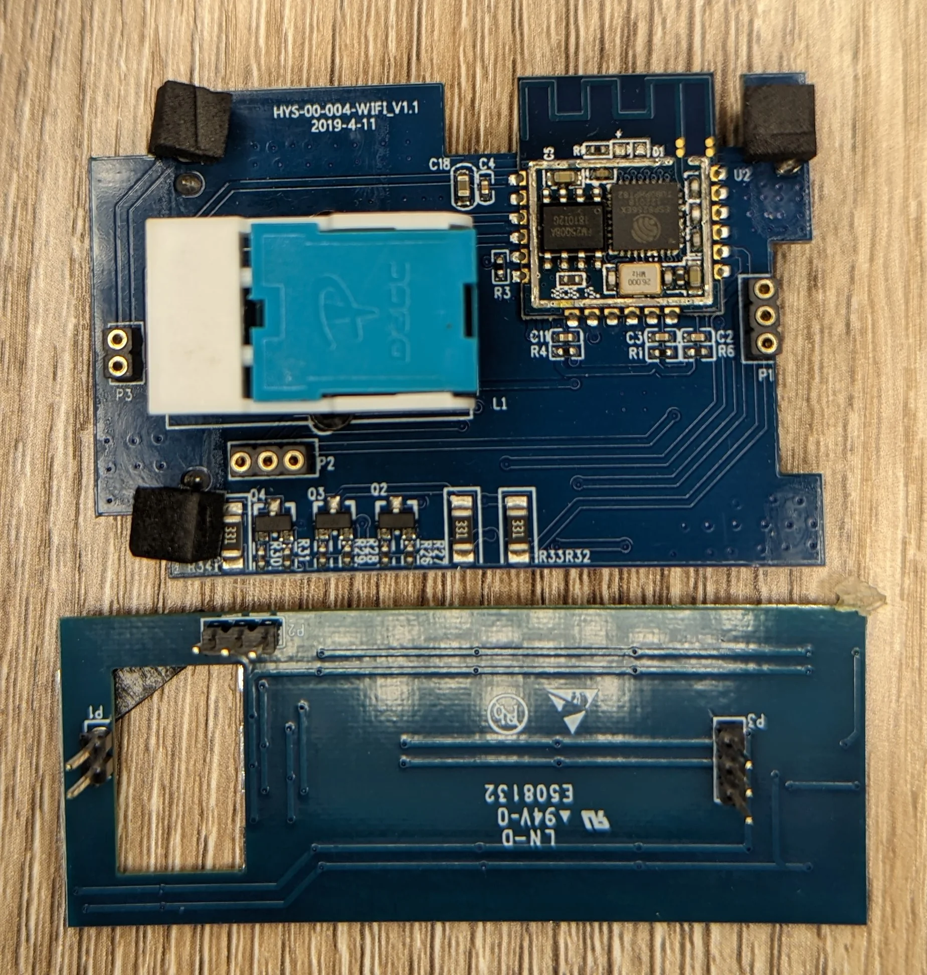
Controller PCB is marked HYS-00-004-WIFI_V1.1 with a datecode of 2019-4-11.
After a bit of reverse image searching, the ESP based module appears to be a WT8266-S1s. The datasheet can be found here.
To save you a click, here’s the useful bit:
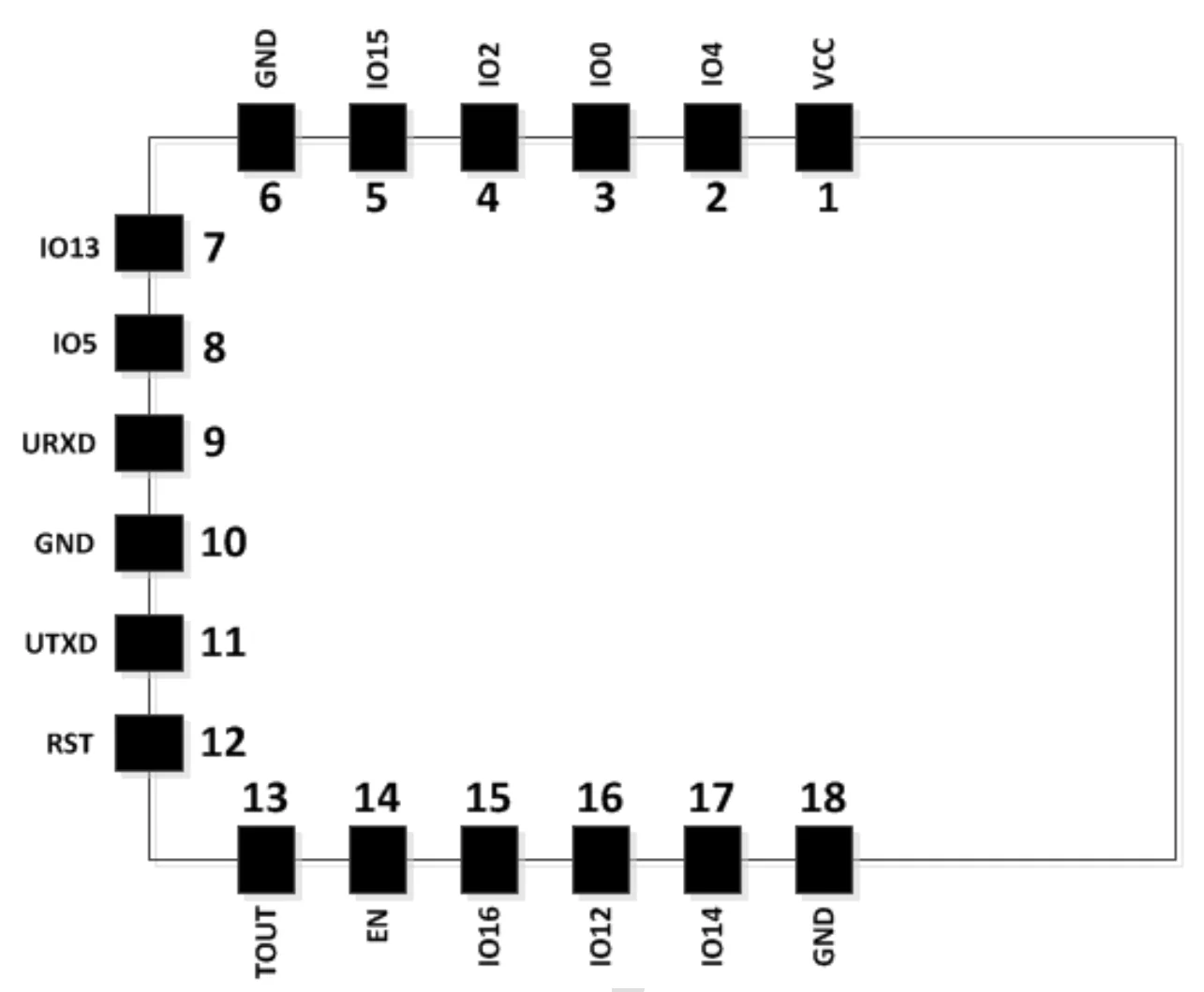
I checked a few of the pins listed on the SSMS118-01AI template switch and they appeared to match the PCB shown above.
Thats all for this one!