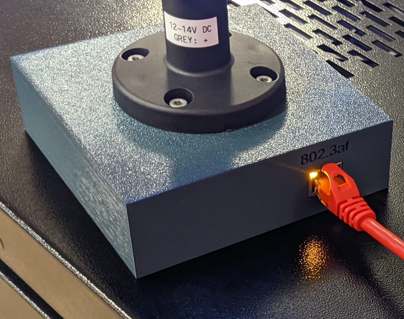
PoE powered Stack Light

The lights are much brighter than they appear in this picture; had to intentionally darken the image to prevent camera from blowing out the colors.
Stack/signal lights are everywhere in industrial applications for good reason: they’re a compact and relatively information-dense indicator system. They always seemed like the kind of indicator that only people with expensive machines needed. Until I found that they can be had for just under $6/light from Ali Express, that is.
I don’t have any giant industrial machines to attach one to, but I do have a non-trivial number of containers/servers/networked-devices running and they all emit various notifications, usually through email. Who wouldn’t mind a novel way to move those notifications beyond email/push notifications into the physical world 🤔?
- 🟢 => Everything is nominal
- 🟠 => Check your email; a
WARNlevel event has occurred - 🔴 => A
WARNorERRORlevel condition has occurred; something (ISP down?) is preventing delivery of notifications so check the logs/dashboards directly - 🔵 => A new
INFOlevel message available in Home Assistant - ⚪ => Not sure; either a “A HIGH priority task is past due” or a ‘modifier’ for above status
While waiting for the light to arrive from China, I started to design something to drive it. It was immediately obvious that an ESP32 module would be ideal to run the show, and just for the fun of it, I decided to make the entire thing (optionally) controlled and powered over Ethernet.
Home Assistant
It wouldn’t be an ESP32 powered project w/o the the fantastic ESPHome framework! With ESPHome comes trivial Home Assistant integration; each individual light / channel on the stack light is automatically configured via MQTT a a light:
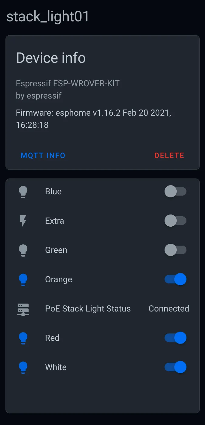
Stack light is controlled via MQTT making it easy to control from Home Assistant or any other program that can speak MQTT.
A slightly modified version of the ESPHome config that I use to build the firmware for the light is attached at the end of this post.
Unfortunately, the one Home Assistant integration that I had in mind is currently not feasible! I wanted to light the blue light when there is any new/unread Home Assistant persistent notifications; a real life “unread” badge of sorts.
There is no way to get the list / count of active notifications unless you’re a websocket client, however.
Using the persistent_notifications_updated event as a trigger won’t work because the event payload lacks useful data; I can’t figure out the number of notifications or their state… just that either notification has been created or dismissed.
If I wanted the blue light on any time a notification was either created or destroyed, I could use this trigger. But the light is no longer a useful indicator; it would be on the first time a notification was created or destroyed and then it would never be off.
Manually trying to keep track of the number of notification created/dismissed actions just feels like a hacky workaround that could easily get out of sync, too.
Oh well 😔.
BOM
I’ll cover the individual 3D printed and electronic components below. Beyond them, you’ll need some additional hardware:
- 4x m3x8mm screws
- 4x m4x8mm screws
- 4x m4x10mm screws
- 6x Neodymium magnets sized 20mm x 6mm x 2mm. These are optional and are leftover magnets from this build
- 10mm diameter anti-slip pads. Thees are optional but will keep the base from sliding around.
I’ve linked to the screws that I used, but any similar ones should work. Strong glue could also work, but is not recommended.
The m3 screws are for attaching the PCB to the printed part (in yellow, below) The shorter m4 screws are for attaching the base (yellow) to the lid (dark blue) and the longer screws are for attaching the stack light to the lid.

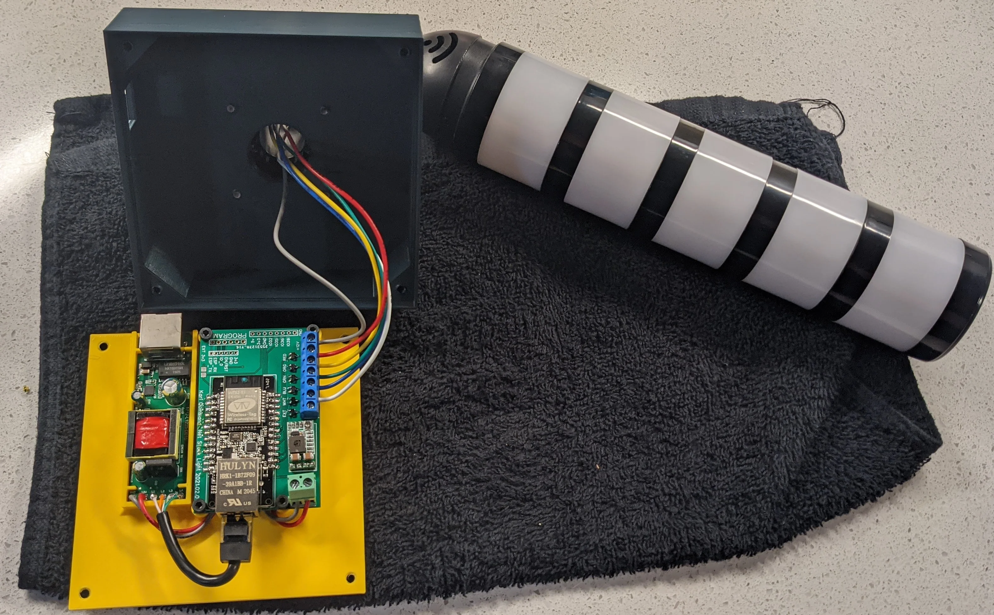
About to start melting threads into the 3D printed parts.
Stack light
Looking quickly through Ali Express, it seems that the lights come in a few different styles, but all appear to be modular in construction. Regardless of lamp style, they all appear to come in 2-5 lamp variants and some have configuration switches that allow for customizing the behavior per lamp.
The ESPHome code and PCB are designed to accommodate up to 6 colors but will work with less.
No matter which style and colors you select, make sure you get one with a positive anode rated for 12V DC.
The exact lamp that I used is here.
ESP32 Module
I chose to use the WirelessTag WT32-eth01 module for the onboard Ethernet circuitry at a relatively cheap price: about $10/module. Bonus: it’s got a breadboard friendly footprint and castellated pads!
You do not need to use Ethernet for control or power; the ESPHome configuration below can be easily modified to use the WiFi.
In any case, you will need a dedicated UART programmer for the module as there is no built-in USB port on the WT32-eth01.
PCB
Nothing much to see here; just a simple board to consolidate connections for what would otherwise be a mess of wires.
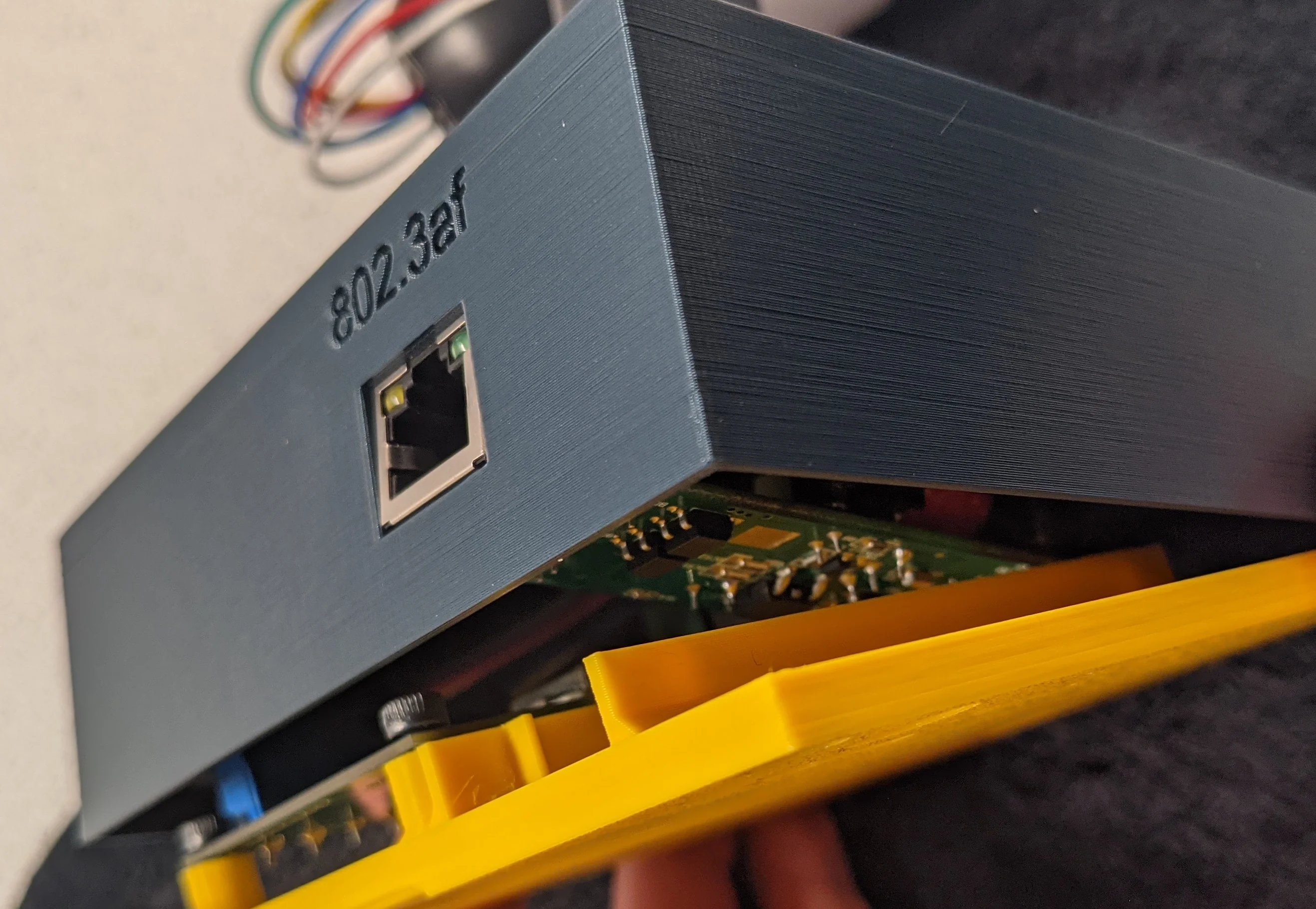
Since I was already using Ethernet for the data, may as well use it for the power, too.
Designing my own PoE circuitry was not in scope for this project, so I went with another off-the-shelf module. I ordered the 12V2A-Full 24W version, but the others are likely to also have an identical internal PCB layout which should fit in the 3D printed parts. Make sure to get one that supplies the 12V that the stack light will need!
The PCB does not care where the 12V DC supply comes from. It wouldn’t be difficult to modify the enclosure to accommodate a USB-C Power Delivery module or even just a standard barrel jack / LED power supply.
Like the PoE module, I use an off the shelf DC to DC converter module to step the 12V down from the PoE dongle to 5V which the ESP32 module requires. That link is to a whole-sale lot of 10 converters. You can order the same module in quantities of one from similar listings. I buy them in bulk because it’s more expensive to design and solder my own on each board that I build…
My testing isn’t super through, but I see the total power draw (measured from the PoE supplying equipment) reaching about 4.5W when all lights are on and about 2W at at idle.
The ESP32 just drives some N-Channel MOSFETS to switch the individual lights on/off. They’re the only surface mount (SOT-23-4) component; everything else can be done with through hole components. The board is designed for up to 6 colors/lights, but populate only as many MOSFETS as you need.
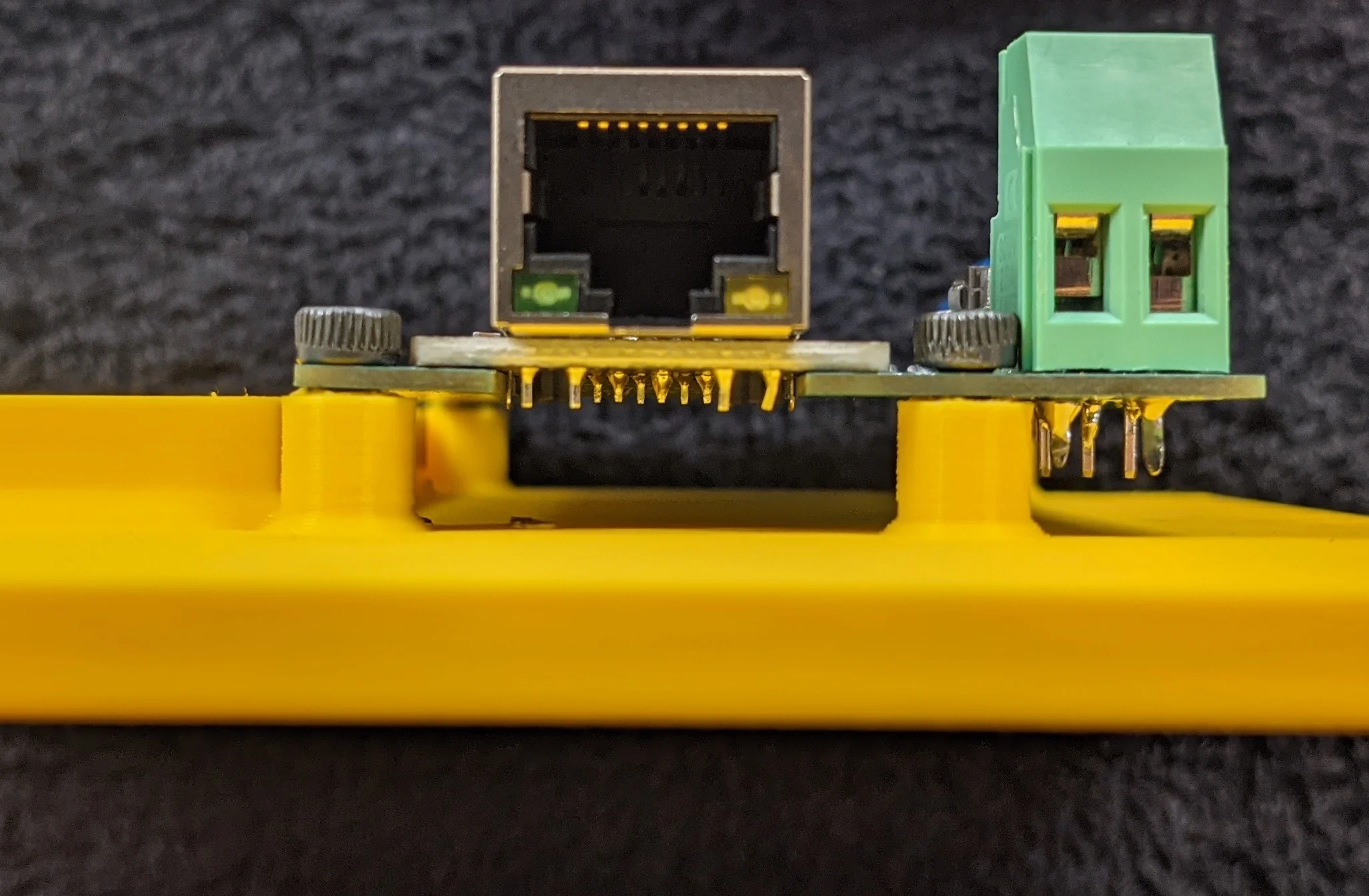
All of the screw terminals are optional; I had several spares left over from a different project, but soldering wires directly to the PCB would work as well.
The 6 pin screw terminal is LCSC part C409139
The 2 pin screw terminal is LCSC part C8463
The source and gerber files from EasyEDA are below. Upload them to your favorite PCB prototyping service or try your hand at making your own.
Printed parts
There are two parts: a lid and a plate. The electronics are attached to the plate and the stack light is attached to the lid. In the photos associated with this post, the lid is dark blue and the plate is yellow.
The plate has features for several attachment methods:
- magnets; meant for horizontal surfaces
- 3M command strip; probably wont be enough to do wall/ceilings, but should work in lieu of magnets on horizontal surfaces
- 4 circular indents (
10mmdiameter) included for anti-slip pads - drywall screw/slot mounting for walls/ceilings
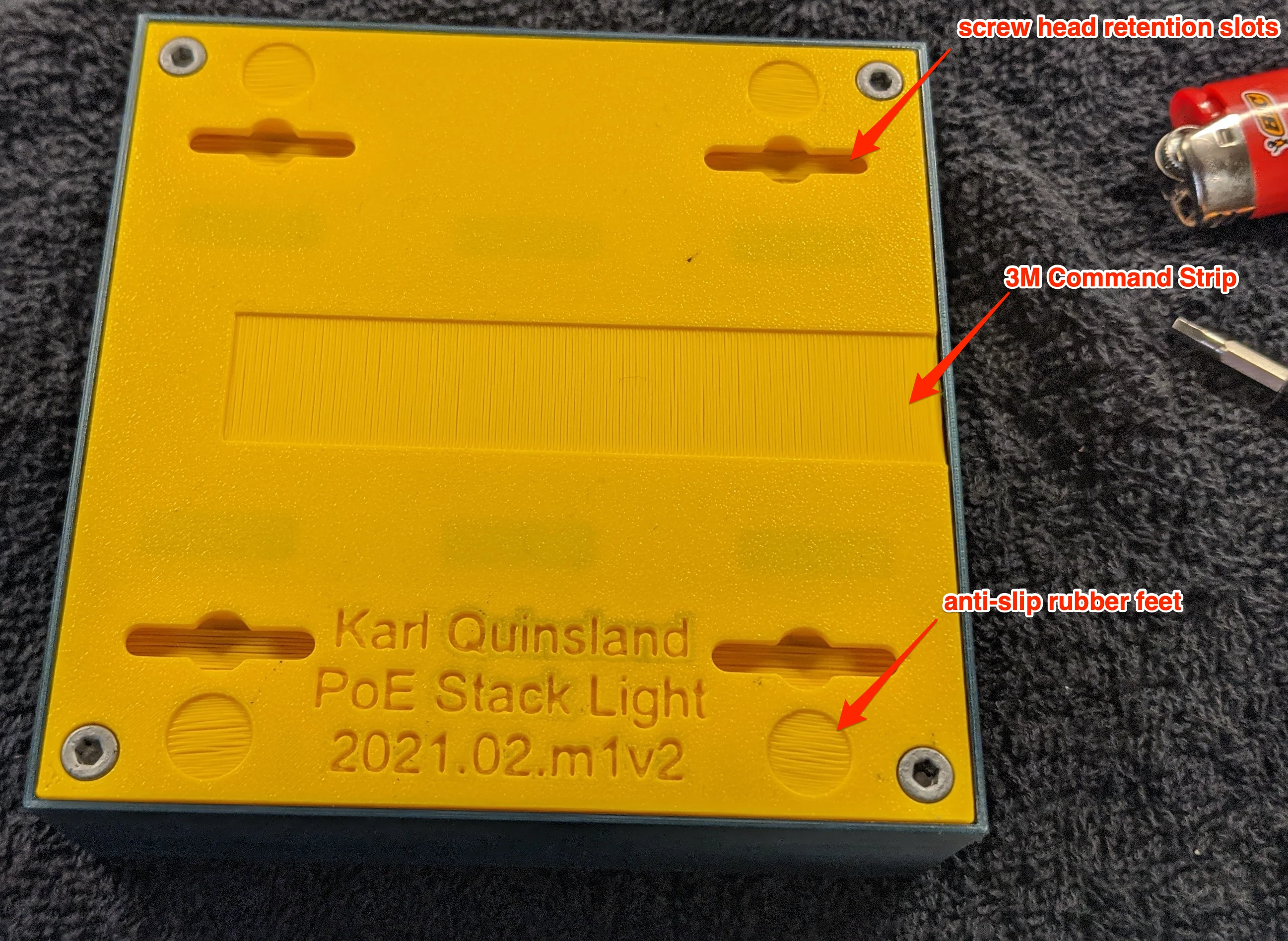
I wasn't sure where I'd want to install this, so there are a few options for attaching the base to surfaces.
Pause the print job at the correct layer if you intend to embed magnets:
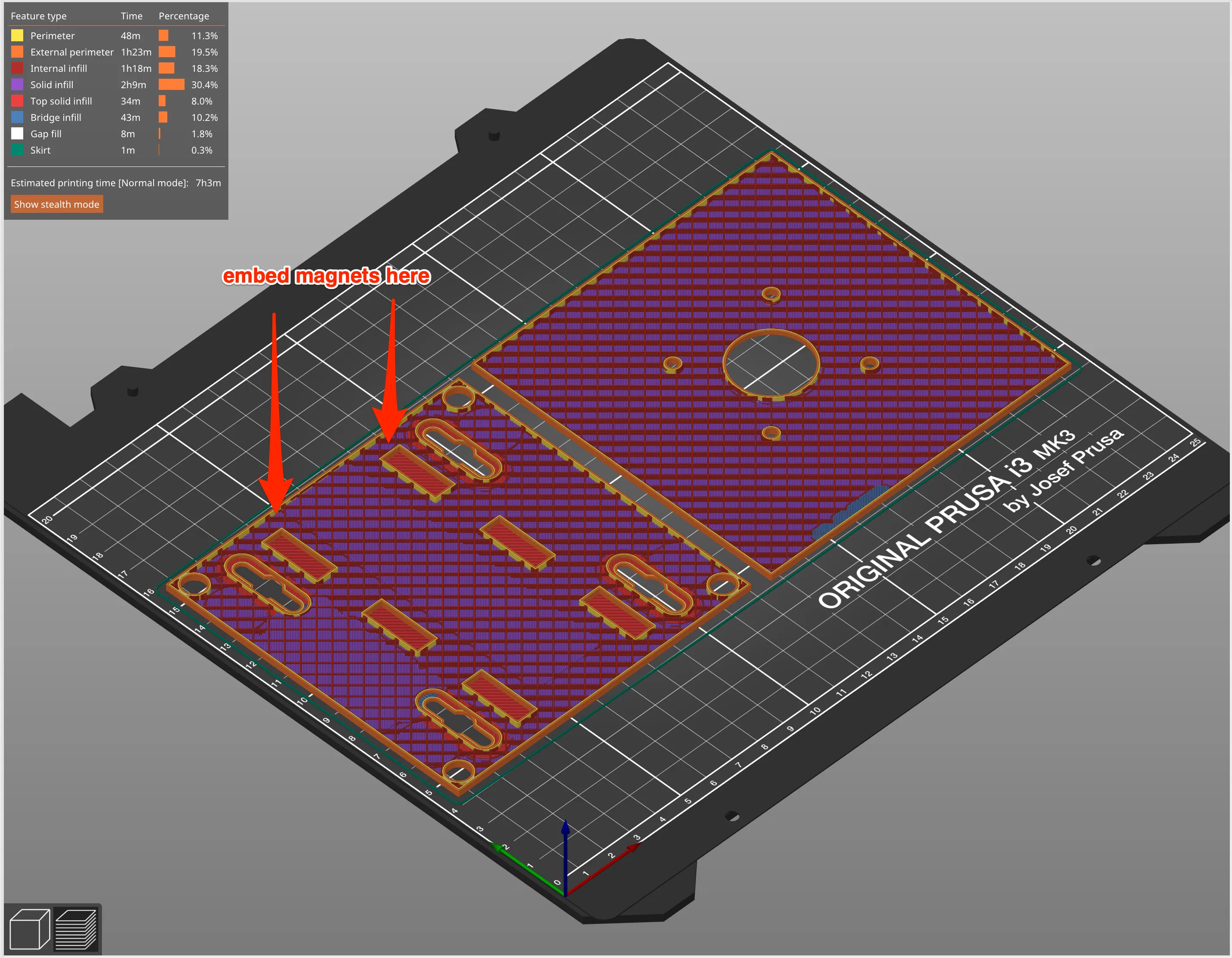
Insert your magnets before the layer covering thee 6 cavities is printed.
Both the lid and base are easy to print; material and color are up to you, as is layer height and quality settings. The stl and step files for both are at the end of this post.
Should you want to make your own enclosure from scratch, I have also included the step files for the PoE dongle and PCB below.
Assemble
Assembly is relatively straightforward; its mostly integrating a few components into a simple 3d printed enclosure.
PCB
Solder the electronic components to the PCB. If omitting screw terminals for the stack light wires, do not solder them to the PCB yet!
I created the castellated pad footprint for the ESP32 module by hand and, in the version of the PCB pictured, didn’t get the pads as close as they should be so there are some ugly solder blobs to compensate. The pads are correctly placed on the most recent PCB revision.
I have included two programming headers on the PCB to flash your firmware; one at 2.54mm pitch and the other at 1.0mm pitch, the latter of which is intended for use with this programmer.
There is a solder bridge labeled EXT 3v3; short this out if you intend to use the programmer to power the ESP32 module. Leave it alone if you plan to use external DC to power the device during programming.
I suggest programming the module now to verify that you’ve built the PCB correctly and that your stack light works as expected. Once you’ve confirmed the electronics and software all work together, proceed to final assembly.
Everything else
The various holes designed to receive screw threads are intentionally undersized. If you’re not using self-tapping screws, you’ll find it MUCH EASER to insert a hot screw for the first time.
With the screw on the end of the driver, hold the tip of the screw/threads under a flame for 5-10 seconds and then quickly rotate the screw into the plastic using a bit of extra ‘pushing’ force. Once the screw is fully inserted, allow it to fully cool (~5min) so the softened plastic has a chance to solidify around the screw threads.
The screws that hold the base plate to the body of the enclosure are meant to sit flush. Ensure that you screw them in fully before the plastic cools!
If the screws protrude even a fraction of a millimeter, the light can wobble and the magnetic attachment is weakened.
While waiting for the screws to cool, cut the Ethernet and power leads from the PoE dongle down to size. Desolder the leads from the dongle, trim to be as short as possible and re-solder.
The less ‘slack’ cable in the enclosure, the easier it will be to finish assembly!
I cut a few inches off the Ethernet cable and power leads so everything fits in the enclosure better.
After the screws have cooled, ensure that the PCB sits flush against the mounts.
PCB should be flush against the mounting posts.
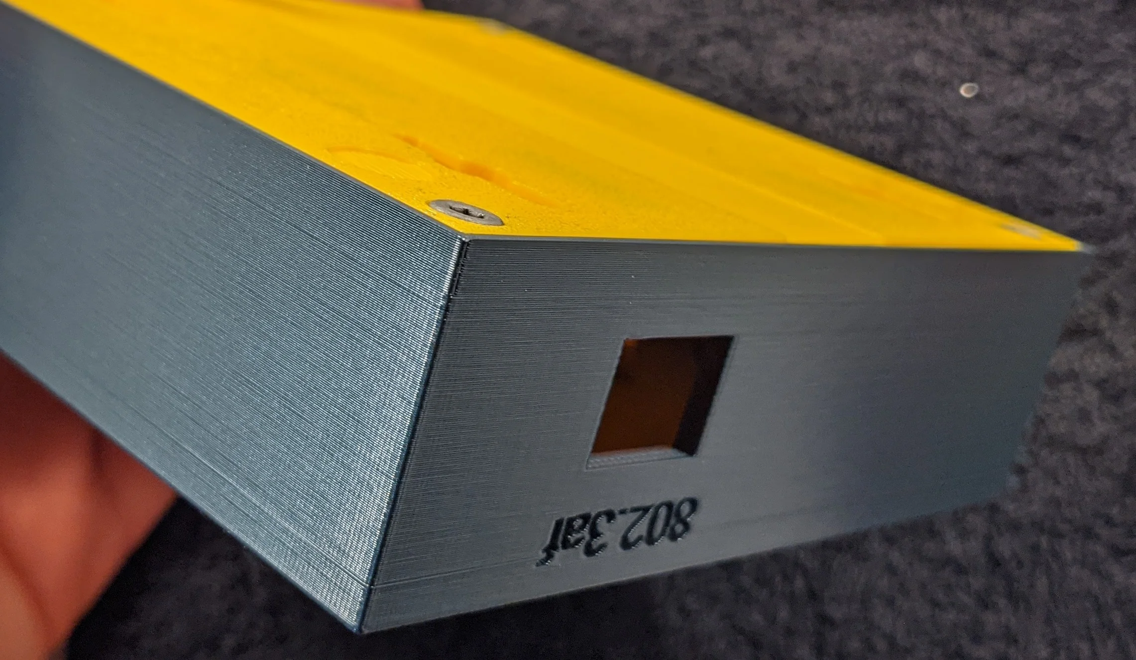
With all wires connected, lift the PoE dongle off of the base plate slightly and align the RJ45 jack with the square hole in the enclosure.
Make sure the side of the base plate opposite the side with the RJ45 jack is securely mounts into the body of the enclosure!
Gently press the remaining side of the base plate into the enclosure. As the base plate gets closer to flush with the body, the RJ45 jack should slowly come into alignment with the wall.
Use the plate as a lever to carefully push, then hold, the PoE dongle in place.
When the base blate is completely installed into the body, the RJ45 jack should be flush with the external wall of the enclosure.
RJ45 jack should be flush to the outer wall of the enclosure.
Attach the base plate to the enclosure body with the 4 screws, attach silicon feet or a 3M command strip and then you’re done!

Translucent white lenses for much less ambiguity than the stack lights with colored lenses.
Files
All files below are licensed under the Attribution-NonCommercial-ShareAlike 4.0 International (CC BY-NC-SA 4.0) license unless otherwise explicitly noted.
None of the files below may be used for commercial purposes
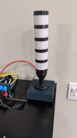
Translucent white lenses for much less ambiguity than the stack lights with colored lenses. 
I wasn't sure where I'd want to install this, so there are a few options for attaching the base to surfaces. 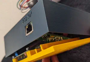
Use the plate as a lever to carefully push, then hold, the PoE dongle in place. 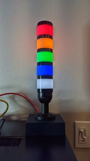
The lights are much brighter than they appear in this picture; had to intentionally darken the image to prevent camera from blowing out the colors. -
files/easy_eda_gerber.zip:
sha1: d7686b0ad88a1686a5a11cb009632b53ca474c75 -
files/easy_eda_source.zip:
sha1: e05a00cdca9af94dd0e8d1d8f3aa998b75c14a08 -
files/enclosure-lid-m1v2.stl:
stl file
sha1: 3870a674d9cf08bf26e3607e42ee766e9816ac6c -
files/enclosure-plate-m1v2.stl:
stl file
sha1: 8f90b54be2a798cf87bc6ca4fc118b82669e0668 - files/esphome_config.yaml: yaml file
-
files/pcb.step:
step file
sha1: e212f3cd3d90a639e6518b7d11bc5cc20df09b67 -
files/poe-dongle.step:
step file
sha1: a698c249d89f2ab2c981427df49620cb09ce5f66 -
files/stack-light-base.step:
step file
sha1: 3c3d0d6162a985b4f09d0f9a58fdacb3f08beb78 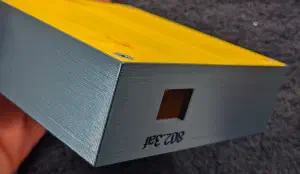
If the screws protrude even a fraction of a millimeter, the light can wobble and the magnetic attachment is weakened. 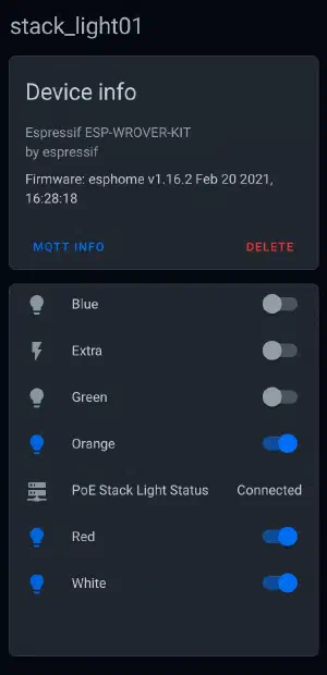
Stack light is controlled via MQTT making it easy to control from Home Assistant or any other program that can speak MQTT. 
PCB should be flush against the mounting posts. 
RJ45 jack should be flush to the outer wall of the enclosure. 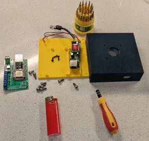
About to start melting threads into the 3D printed parts. 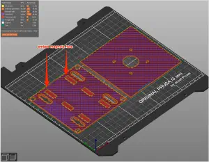
Insert your magnets before the layer covering thee 6 cavities is printed. 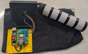
I cut a few inches off the Ethernet cable and power leads so everything fits in the enclosure better.


