Quick look inside the OMRON Evolv BP7000 Blood Pressure cuff
A friend recently asked for my help with some reverse engineering. They wanted to know how difficult it would be to re-use some components from a lot of refurbished blood pressure cuffs they had recently acquired.
Sounds easy, right? At a high level, there’s going to be:
- a pump and a pressure sensor and a valve
- a micro controller to run the show
- a way to communicate the readings back to the user
In the interest of expediting things, I asked for the FCC IDs from the devices so I could have a look inside… and was surprized to find out that there was no FCC listing for this particular model from the lot.
😕

Here's what it looks like on the outside
So with that out of the way, here’s what the Omron BP7000 looks like on the inside.
Teardown
There are a total of 7 philips screws holding the unit together. Two of the six are much smaller so two different sized bits might be a good idea.
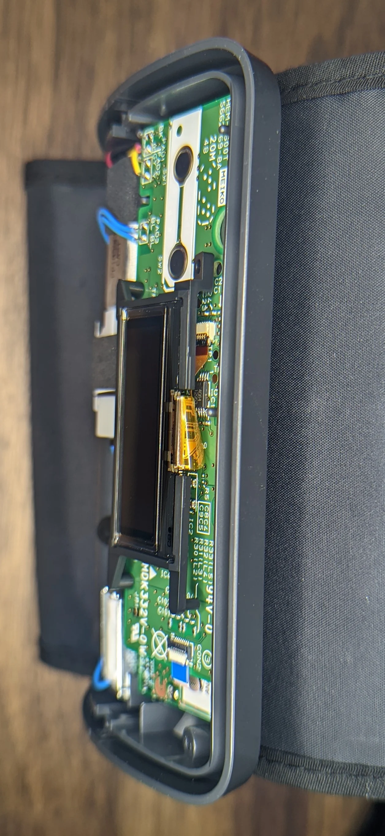
After removing all the screws and carefully prying back the plastic clips, the front panel comes off of the body giving us the first look at the PCB stackup and mechanical internals.
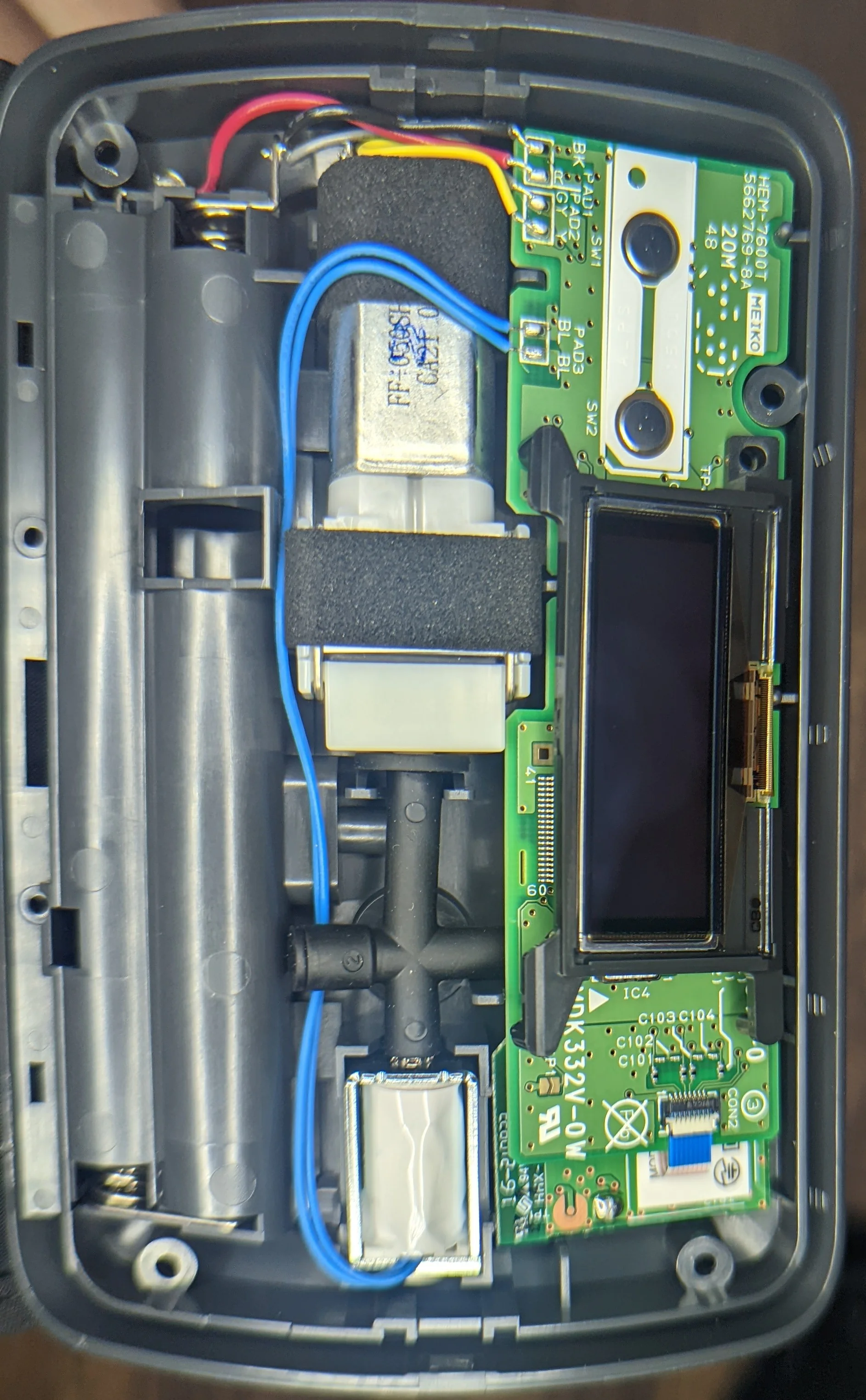
The OLED screen is not held in place with anything so be exceedingly careful when opening!
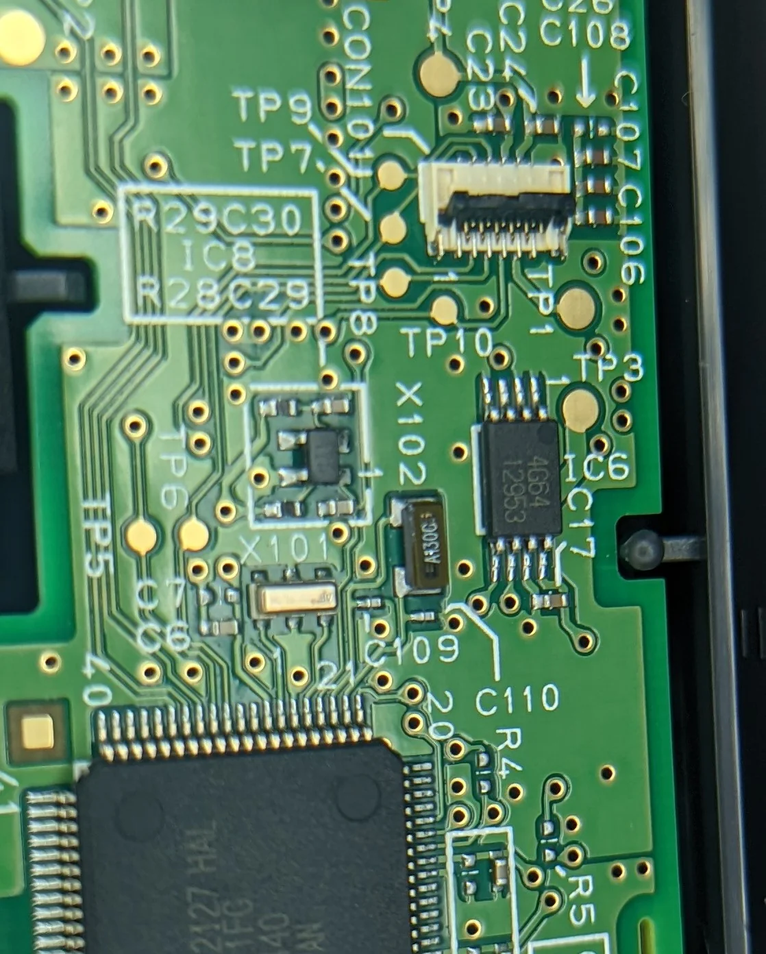
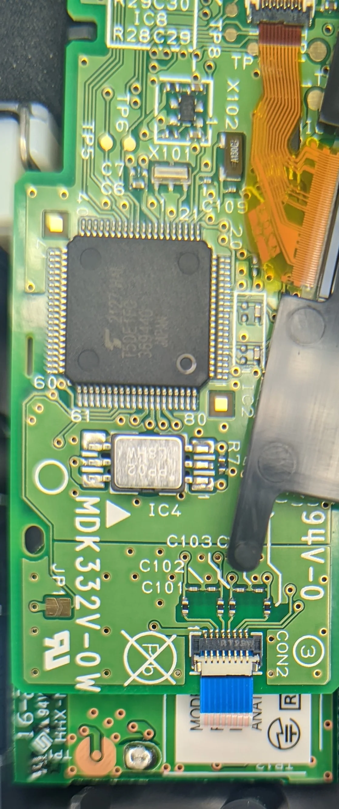
Here’s a closeup of the ‘front’ of the main PCB. There’s a ton more passives than I thought there would be but a single large controller next to a pressure sensor is about what I figured.
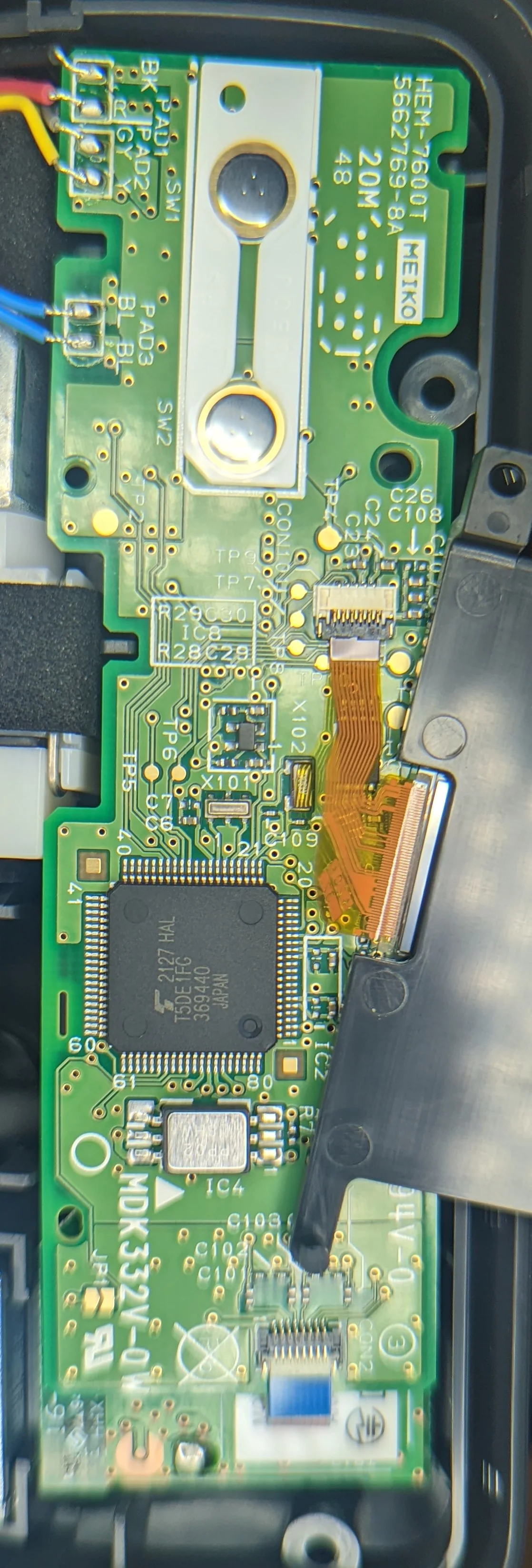
Details on the ICs are below.
I am not quite sure what this little IC is for. Calibration or firmware?
The BTLE module is connected through a 8 wire FFC.
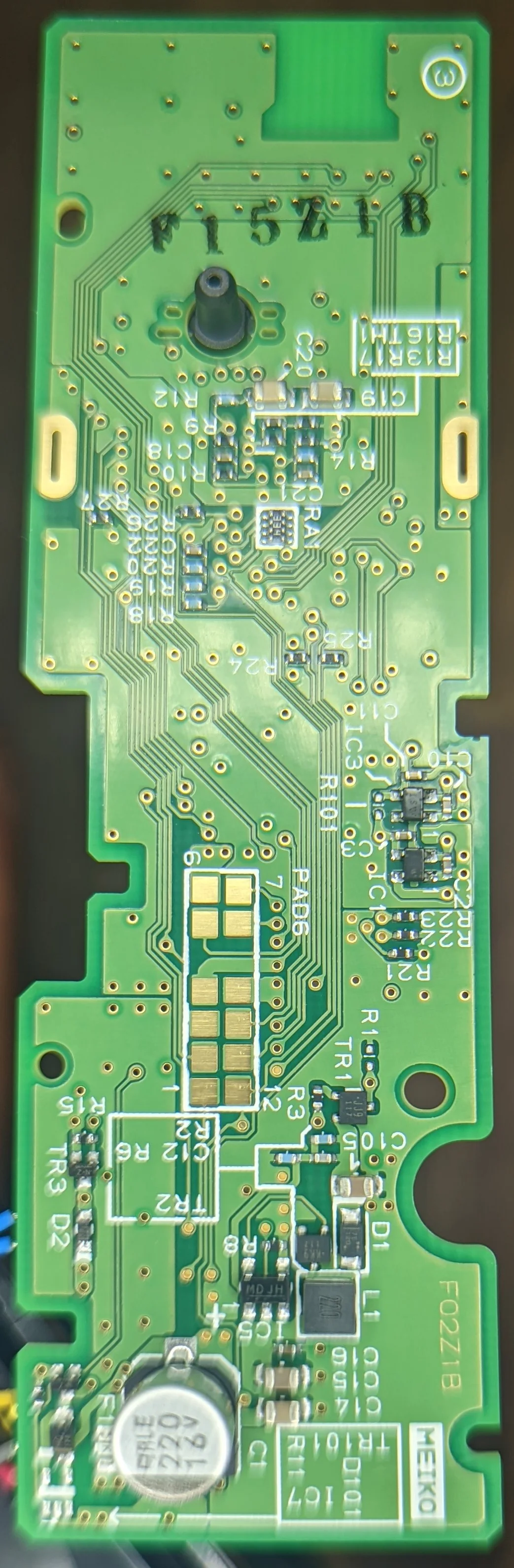
Several of the square pads are accessible from the exterior before the pressure cuff is attached. Almost certainly for programming at the factory.
With the main PCB removed, you can see the actual mechanical components that build up and release the air pressure. The two blue wires are for the solenoid that vents air pressure out of the system. The port to the right and just above the BTLE module is where air pressure is measured. The white box attached tot the motor is the air pump.
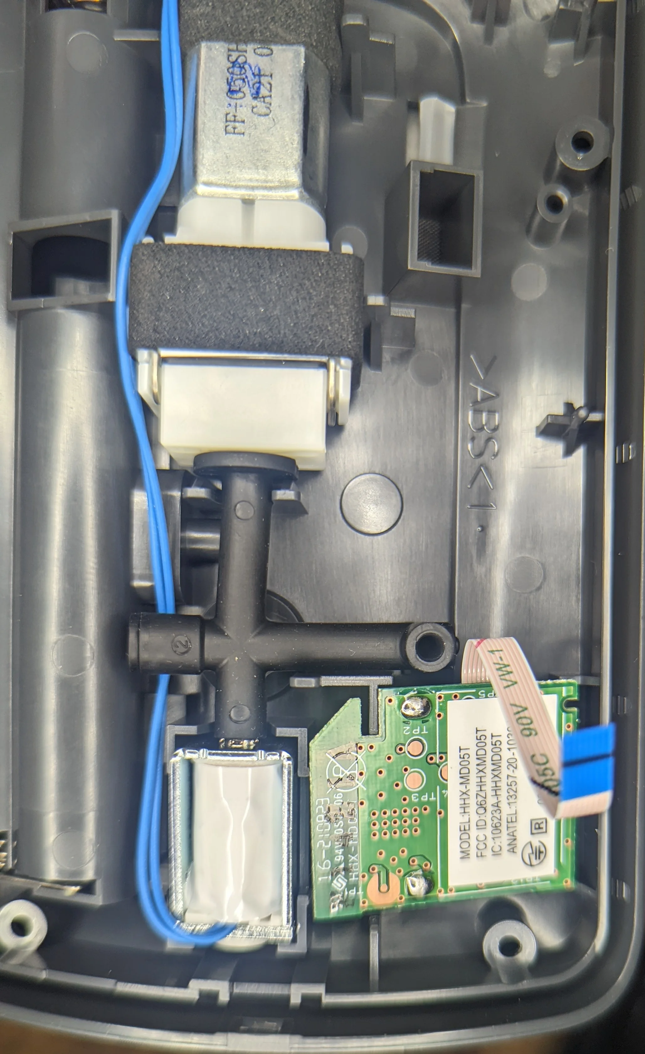
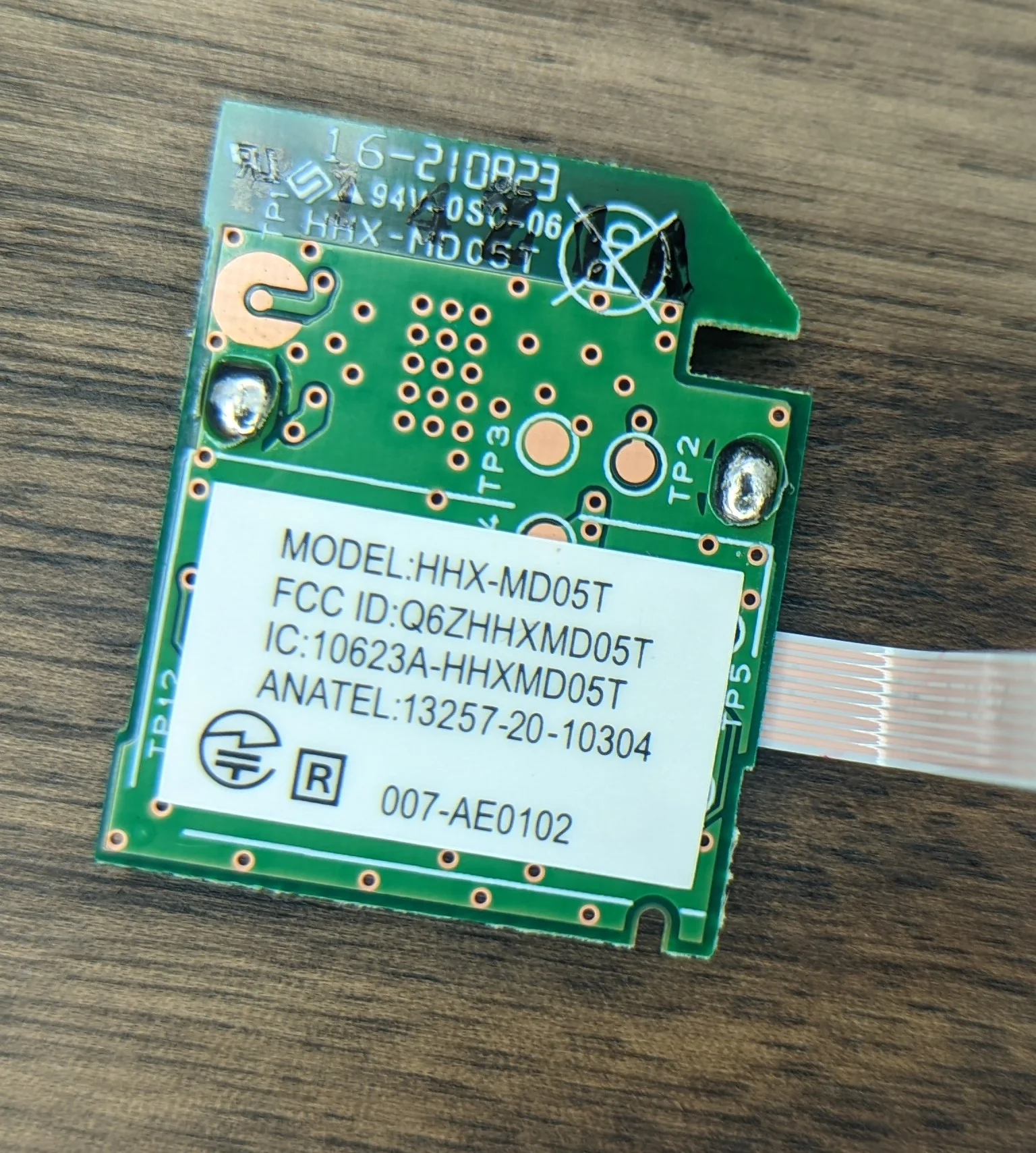
BTLE module
For some additional photos of the module w/o a shield, check the amazing fccid.io page.
This module appears to be used in several similar blood pressure monitors.

PCB Markings
AKA SEO optimization 😉
Main PCB is marked:
HEM-7600T MEIKO 5662769-8A 20M MDK332V-0W
And on the rear:
F02Z1B F15Z1B
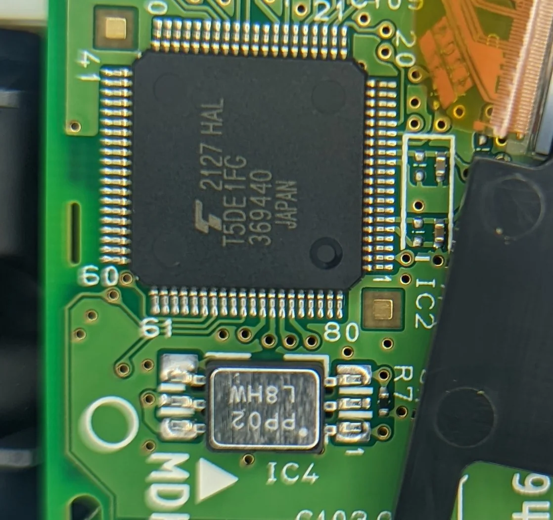
The main CPU is - apparently - from Toshiba and marked with:
2127 HAL T5DE1FG 369440
I can’t find anything specific. The only result in google is this spreadsheet. If you look closely, you’ll find the string T5DE1FG (TOSHIBA) in column L on rows 1254 and 1255.
The pressure sensor is labeled:
PP02 L8HWwhich appears to be an Omron made sensor.
The small 8 pin IC adjacent to the main processor is labeled:
4G64 12953
BTLE PCB is marked:
MODEL: HHX-MD05TFCC ID: Q6ZHHXMD05TIC: 10623A-HHXMD05TAnatel 13257-20-10304007-AE01029545448-2A