Inside a generic/white-label HDMI KVM Switch
If you’re here just for “how do I get it working with ESPHome” bit, skip to the ESPHome Component section below.
For the last few months, I have been looking for a KVM switch to simplify switching between work and personal computers. Initially, I didn’t think my criteria were that unreasonable, but for whatever reason there is no KVM switch that:
- Supports at least 4 hosts. Preferably dual monitors per host to ensure relevancy for years. Converting between HDMI and Display Port isn’t that difficult so no strong preference as long as the KVM uses HDMI2.0+ or Display Port 1.4+ as my primary monitor is 4k.
- USB 3 support. At least 5 gbps and Ideally using a USBC jack.
- Some sort of programmatic control over which host is ‘active’. Ideally this interface would be bi-directional (RS232/RS485 or IP) but I’d settle for having to record the IR remote codes and re-broadcast those with my own microcontroller if needed.
- Works with the DROP: SHIFT keyboard; internally this keyboard presents as it’s own USB Hub and requires more than the standard 500ma to operate. Some KVM switches don’t supply enough current and others results in the number of USB hubs between the root and the keyboard being > 5 which the USB spec does not support.
- Costs less than $75 per host/port.
Try as I might, I was not able to find anything that could satisfy all the requirements. If you know of any, please do get in touch!
I spent a decent chunk of time searching through the usual consumer/IT electronics sites and they all had similar offerings… none of which were sufficient. I had some close contenders, but they are victims of the current chip shortage or otherwise very expensive unobtanium.
I recently read USB-C hubs and my slow descent into madness - Dennis Schubert which prompted me to broaden my search horizons to include the marketplaces closer to where all the KVM switches I was seeing in my searches were actually designed.
After a bit of searching, I found the PX-UHDKVM801-2.0:
A single video channel isn’t a deal breaker; ultra wide screens can render more pixels off of one HDMI port than 2 screens from a few years ago could. Assuming this continues, by the time my current monitor dies dual video might not matter at all. Likewise, speedy USB is a “nice to have”. My keyboard, mouse and web cam must work with the KVM. If the webcam streams in SD over USB2 but full HD over a USB3 link that’s a nice benefit but not a deal breaker. For the occasional times where I need to transfer a file and can’t do it over the network, I can either plug directly into the host computers’ USB3.2 port or settle for slow USB2 file transfer speeds. Not the end of the world!
Of all the KVMs that I considered, this one came with the least compromises and came with explicit documentation about how to integrate/control the switch via TCP or RS232. Buoyed by the thought of not having to reverse engineer any IR remote codes or otherwise resort to some hackery, I pulled the trigger.
I say “generic” because there are a few different brands / names on this thing and it’s not clear who the actual manufacturer is.
I got it from a seller by the name of PourXuan which does seem to be the OEM behind it.
However, there are a few other interesting markings that could indicate other companies contributing to / designing some internal components.
Anyways, lets look inside.
Teardown
TL;DR: It’s been built down to a cost… but not the lowest possible cost. The construction isn’t flimsy and I didn’t find any glaringly obvious safety issues / construction shortcuts. None of the ICs have their markings scraped off and the internal architecture is simple and scalable. I did not check, but I suspect that each of the primary functions / PCBs communicates over a simple serial bus so this switch is likely pretty hackable/serviceable, too.
Packaging / shipping
The switch came well packed in some nondescript packaging.
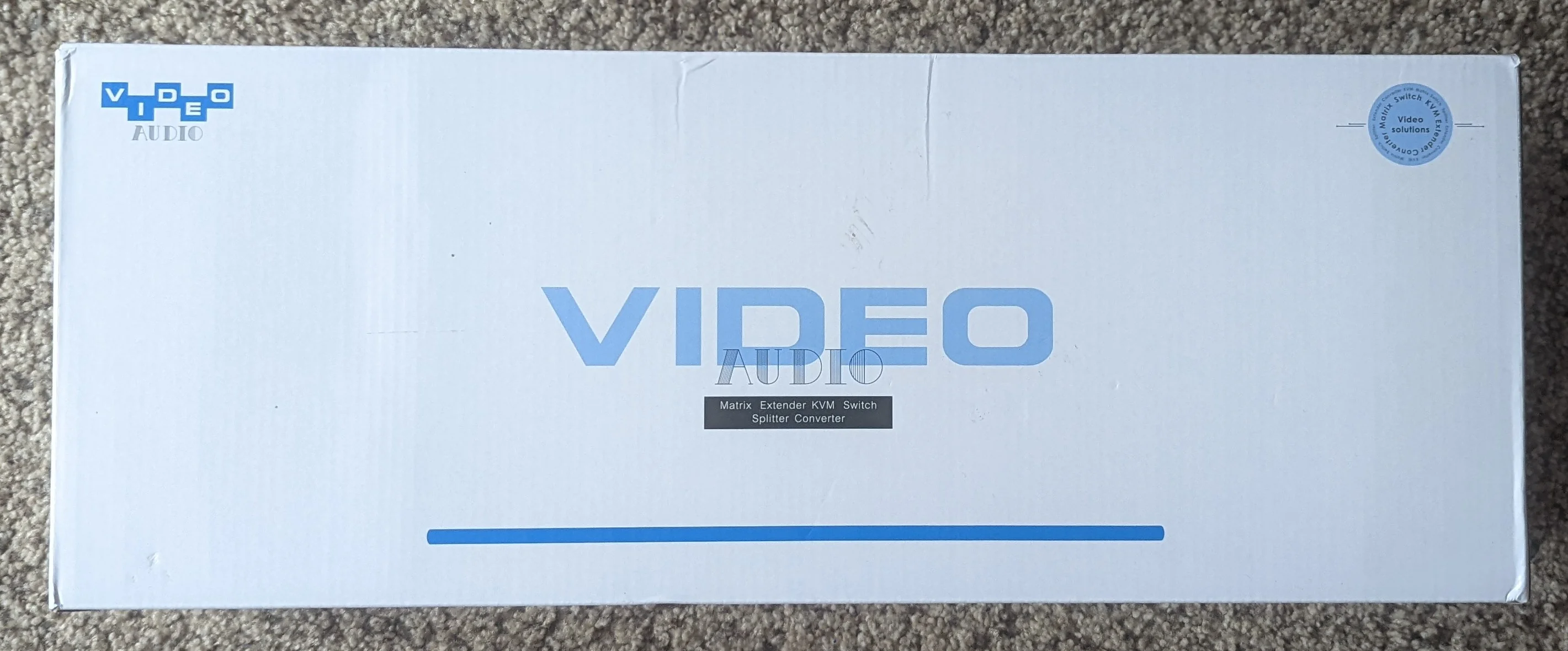
The small white box containing the power supply and some accessory hardware crumpled up the single page user manual.
I have uploaded a copy of this paper and the other software/documentation provided by the seller to the same git repository hosting the ESPHome Component.
An overview of everything that came in the box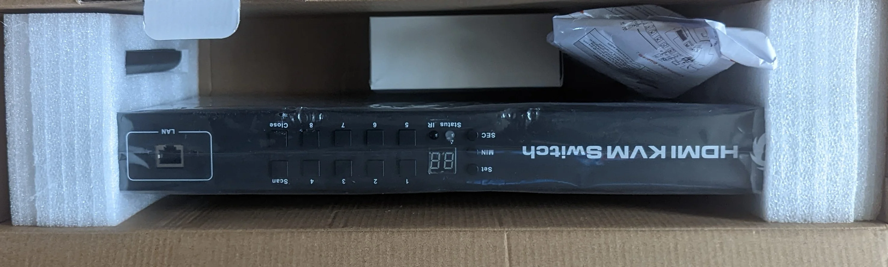
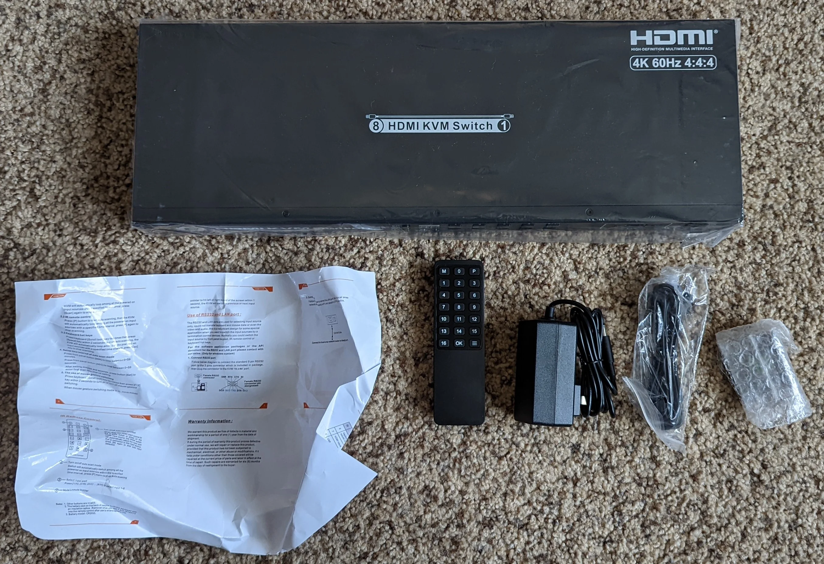
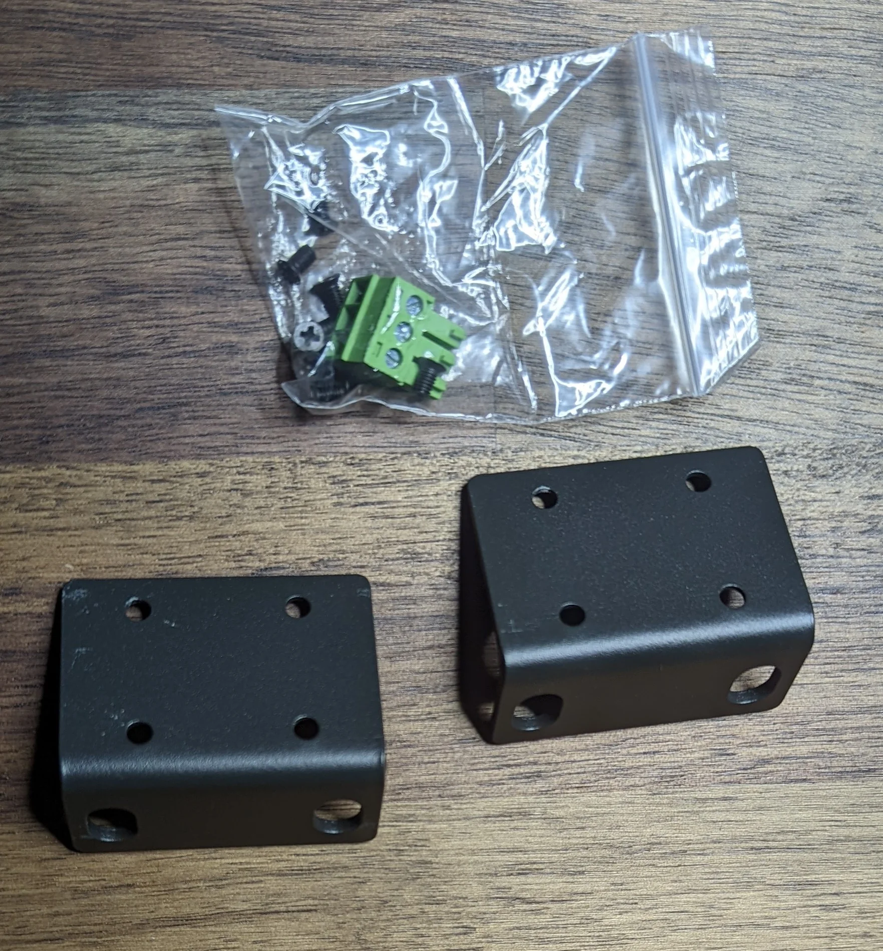
Rack Mount ears, two extra screws and the proper connector block needed to interface with the UART.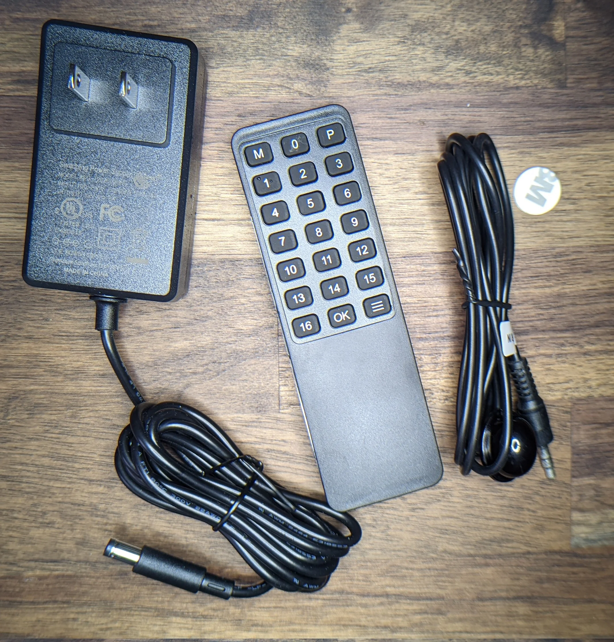
I have not opened up the power supply to check its construction but it doesn’t feel incredibly cheap. It’s rated for 2 Amps @ 12v but the switch only drew about 3.75 Watt when measured from the wall.
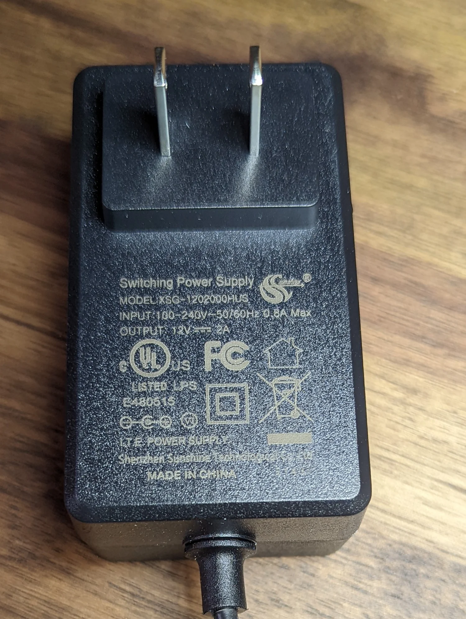
Nothing special. It doesn't feel cheap.
The switch
The metal shell is generic; there are holes on the side for ventilation fans that are not populated. Other than not-so-well hidden screw, the case is easy to open.
Don't forget the screw behind the sticker
With all screws out, the two halves slide apart easily to give us the first look at the internals!
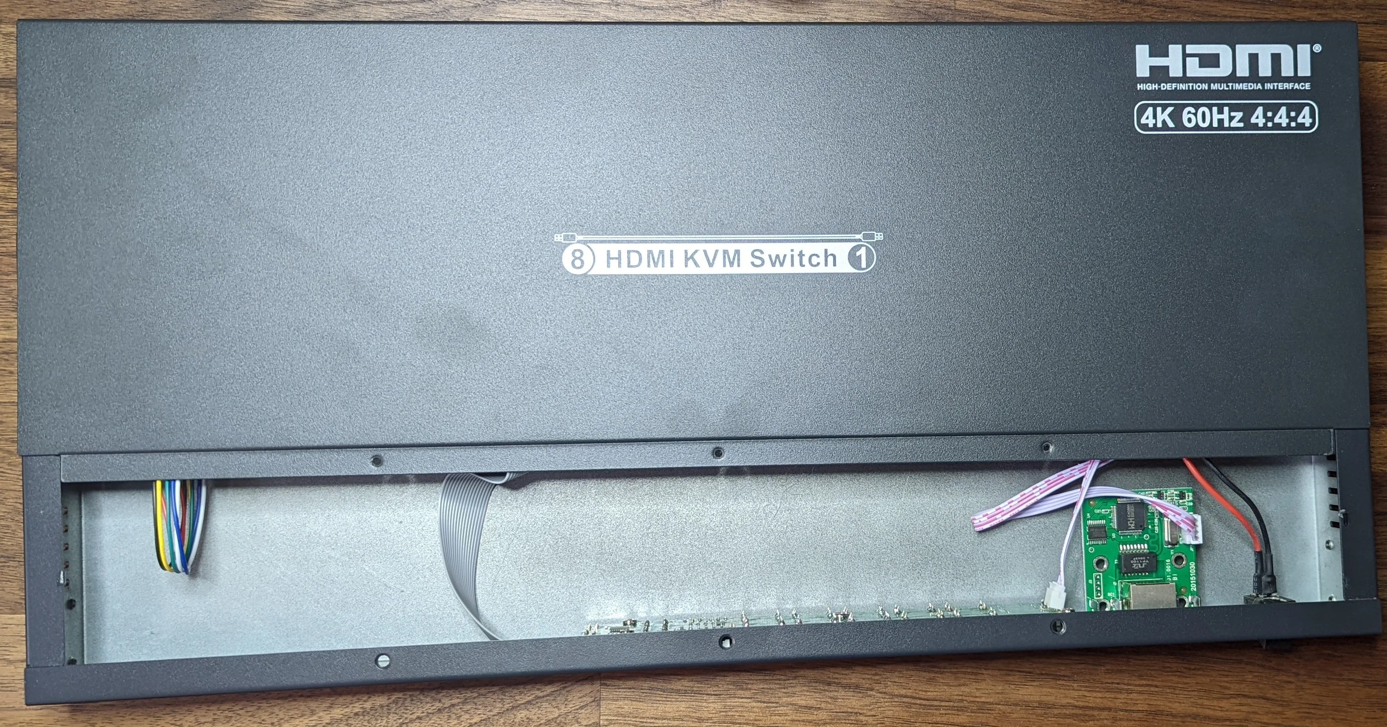
It looks like this is a pretty modular design:
- A standalone front panel input and network control.
- A dedicated PCB for each type of data; a HDMI/video plane and a HID/USB plane.
- Each plane uses dedicated ASICs to route the signals.
- A minimal number of microprocessors / wires coordinating between the PCBs.
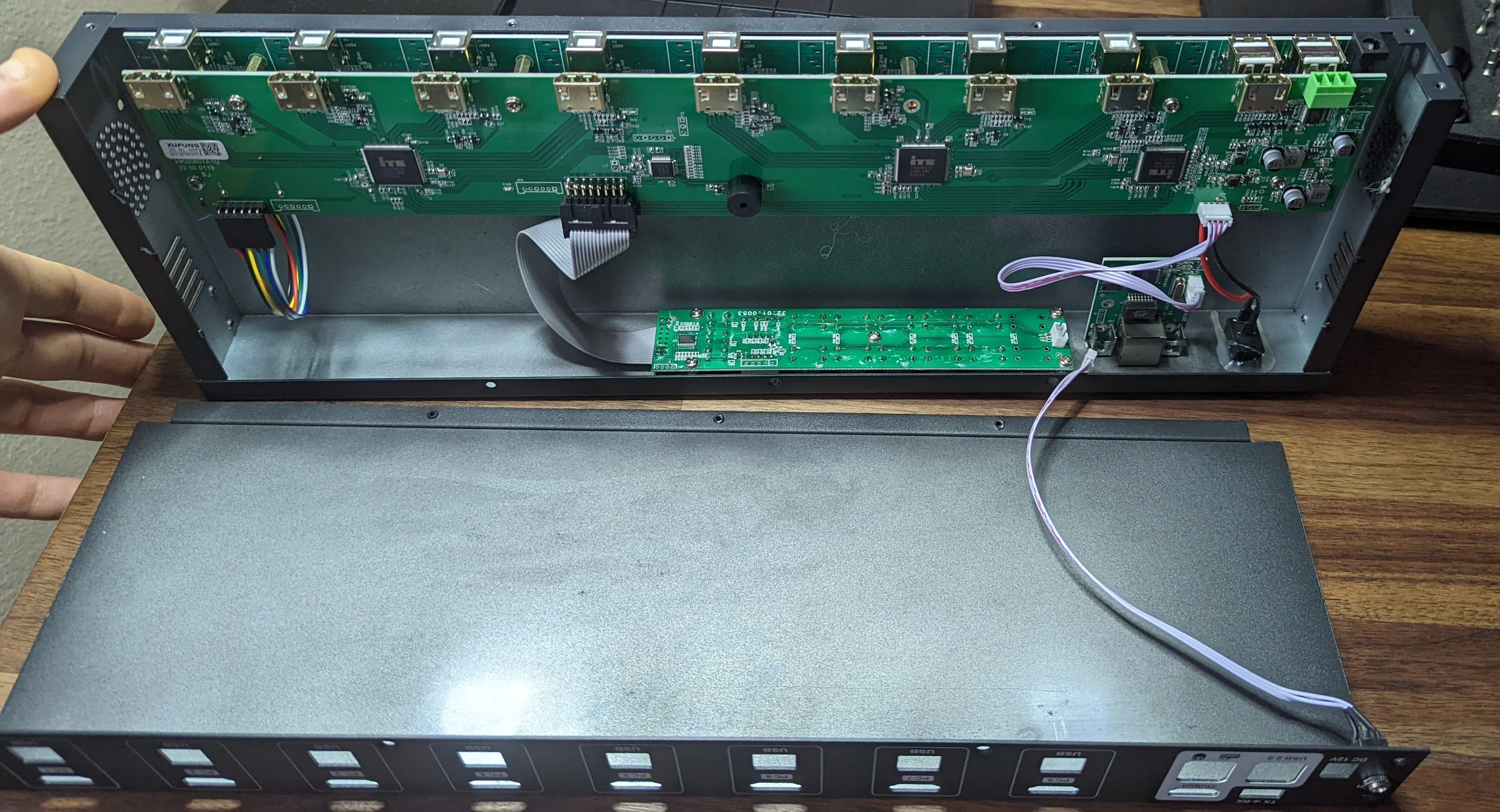
The small cable from the IR jack on the back is all that holds the two halves of the case together.
The LAN module plugs into the HDMI PCB very close to where the RS232 port is and the protocol specific documentation from the seller indicates that the payloads to control the switch are the same irrespective of the transport.
Each group of 4 HDMI ‘inputs’ is routed to an identical looking IC and the differential signal pairs from those ICs are routed to the big one next to the output and RS232 and LAN circuitry.
The little micro next to the buzzer and grey ribbon cable is likely the main controller for the entire switch. The small IC on the front panel is probably watching for IR signals, scanning the physical buttons, driving the LED display and communicating with the rest of the system over some serial bus.
This architecture would be pretty scalable; for a 16 port model, just add another HDMI and USB PCB and tweak the firmware on the main controller.
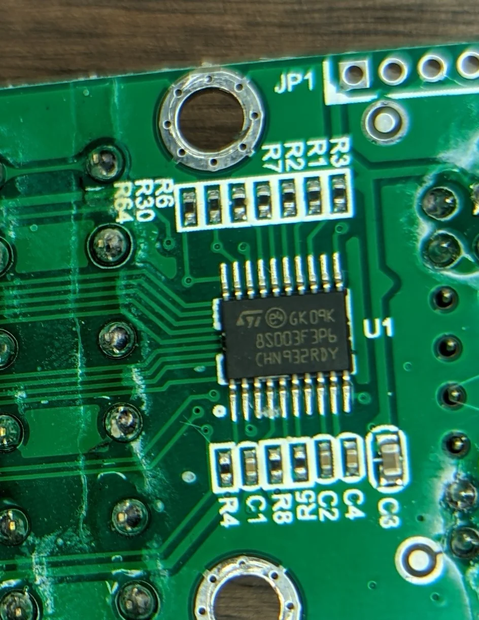
Front PCB
Nothing particularly interesting here. The single IC (STM8S003F3) is a cheap 8 bit microcontroller that - based on the PCB traces - is driving the LED display and handling the button matrix scanning and IR codes.
Most of the lines from the grey ribbon cable are not actually connected to the pcb so I’d bet that this micro communicates with the ‘main’ PCBs over some serial bus.
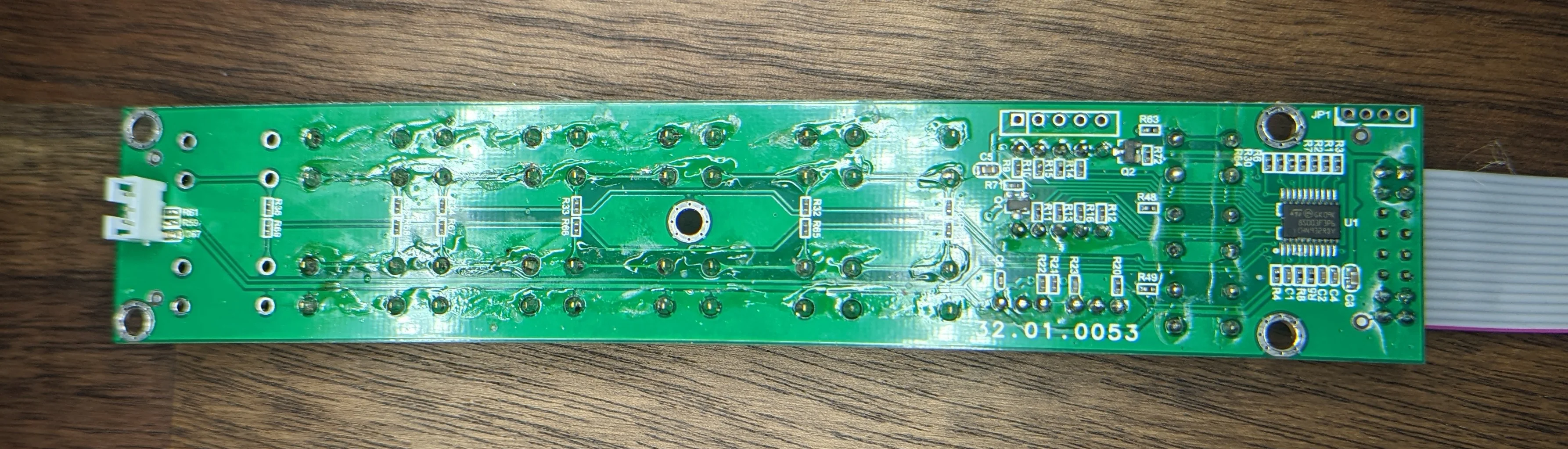
Sorry for the glare. There's a lot of flux residue on this PCB.
Notice how at least 4 of the pins from the ribbon cable connector are note soldered to the PCB...
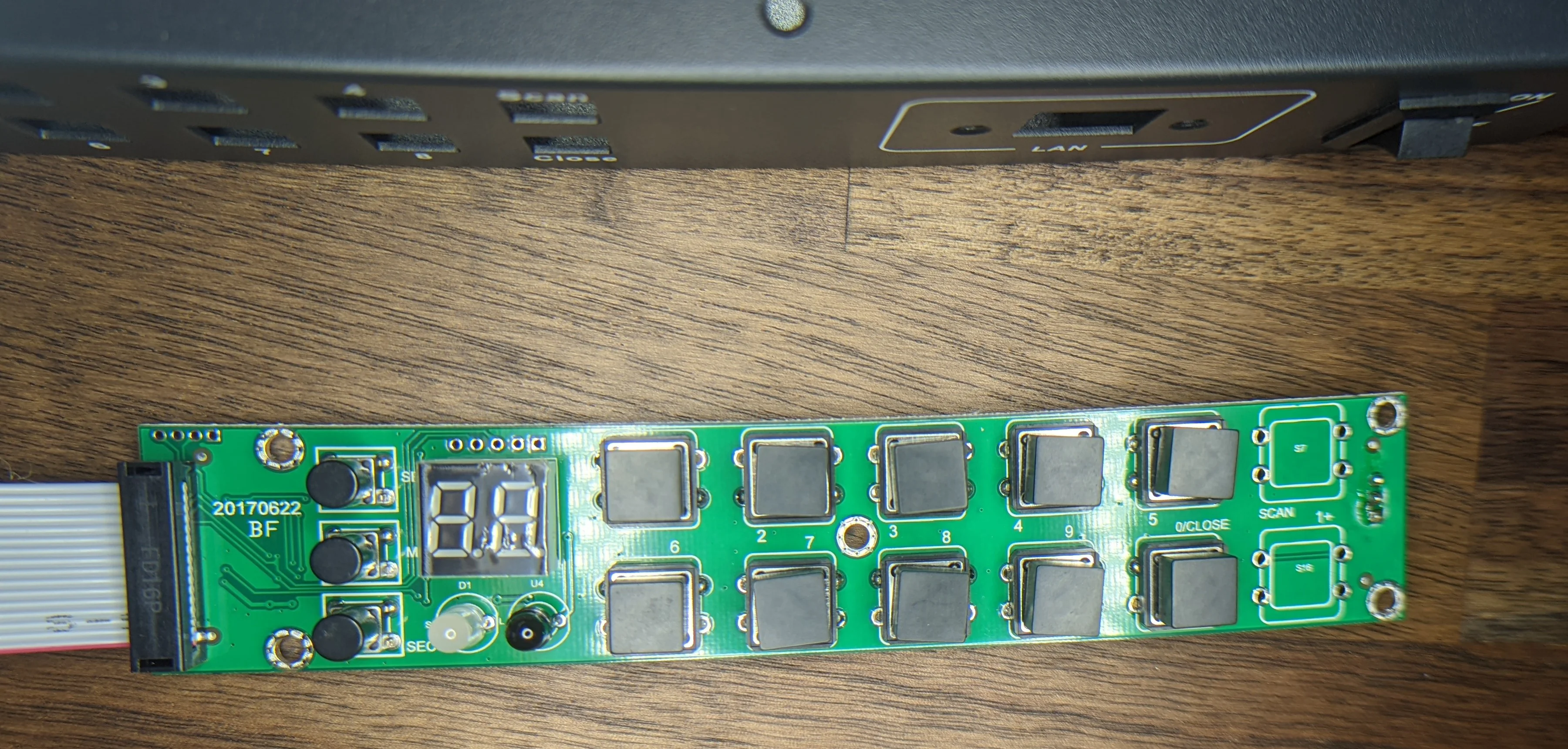
This PCB is means to be used in other SKUs that come with two extra buttons that are unpopulated here.
The LAN module
Very simple / standalone module. There’s a dedicated PHY (CH395Q) and the same STM8S003F3 micro controller again. The documentation that I received from the seller indicated that the LAN module did NOT use DHCP and there didn’t seem to be a way to change the IP address configuration so I didn’t bother with trying to automate via LAN.
Only after I made it most of the way through the ESPHome integration development did the seller provide additional documentation that indicates the IP address can be changed… but only if you use a Windows program. I opted to keep going with the ESPHome <-> RS232 integration as that would be the most flexible and accessible approach.
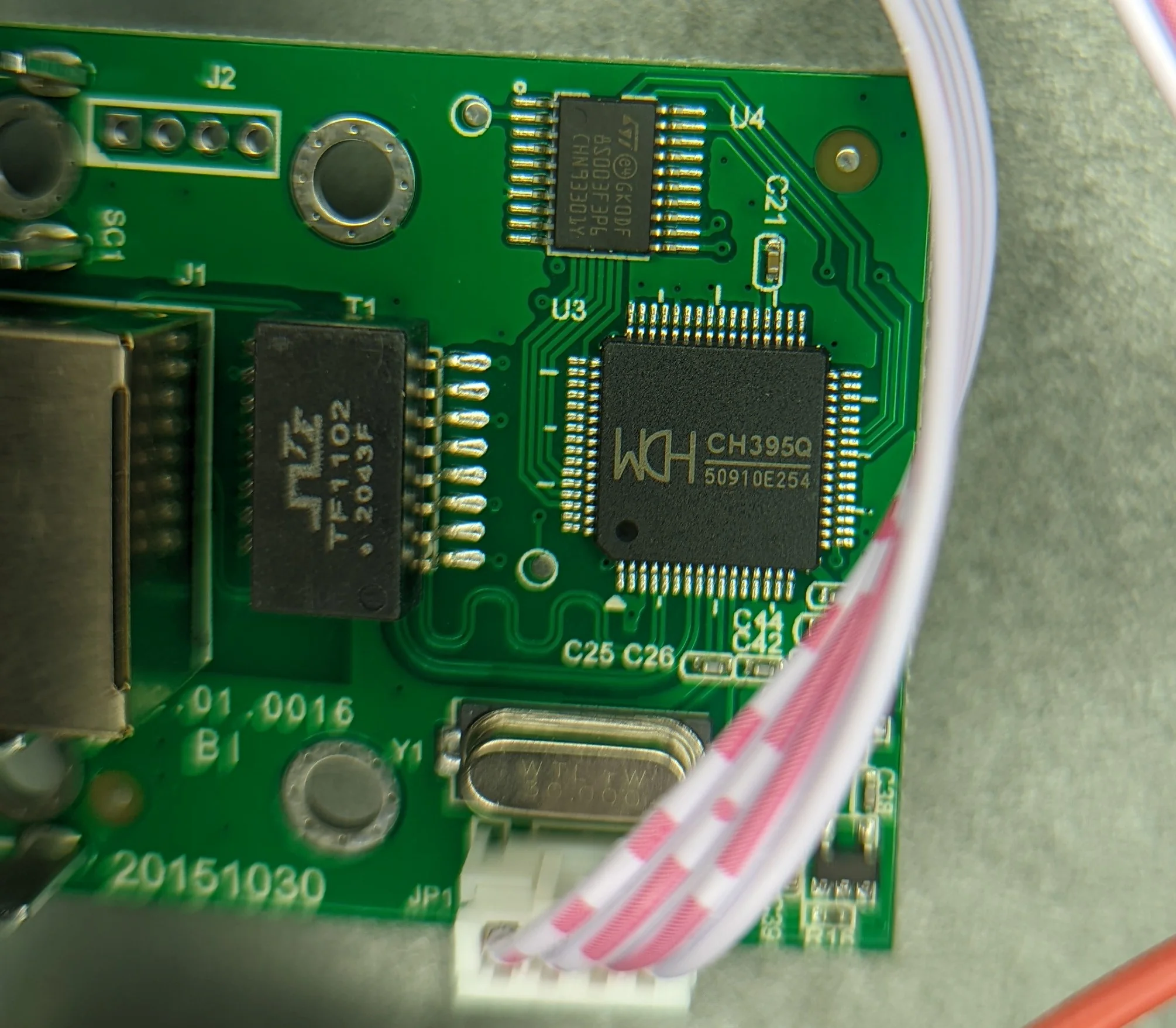
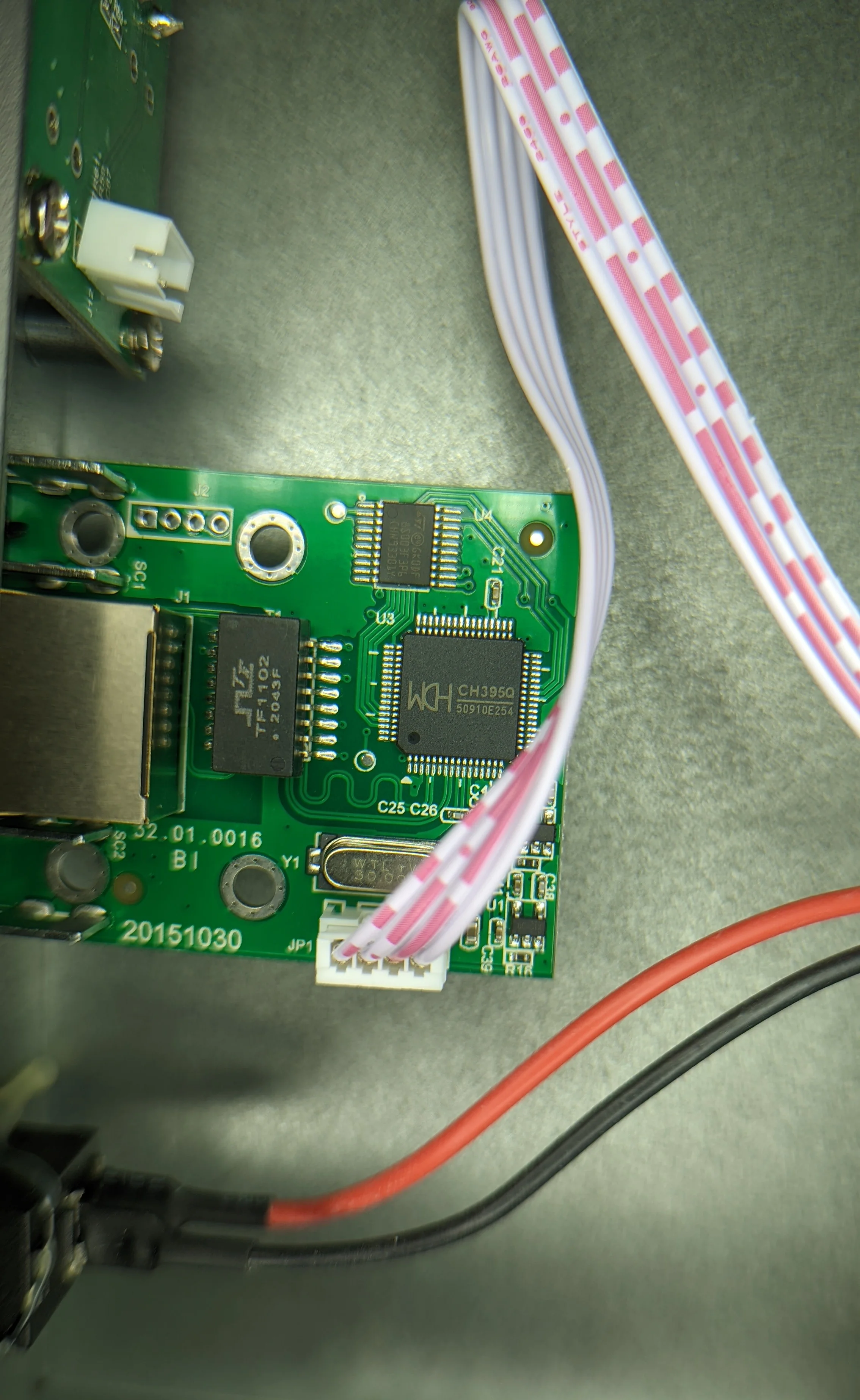
The small LAN pcb is attached directly to the front panel with screws mating with some 90 degree flanges soldered to the PCB
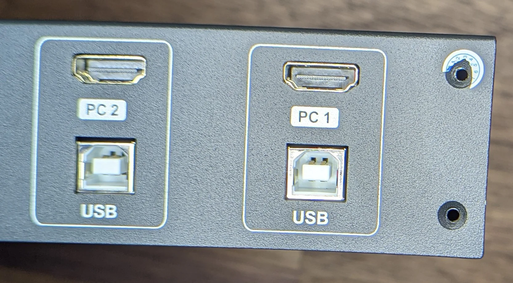
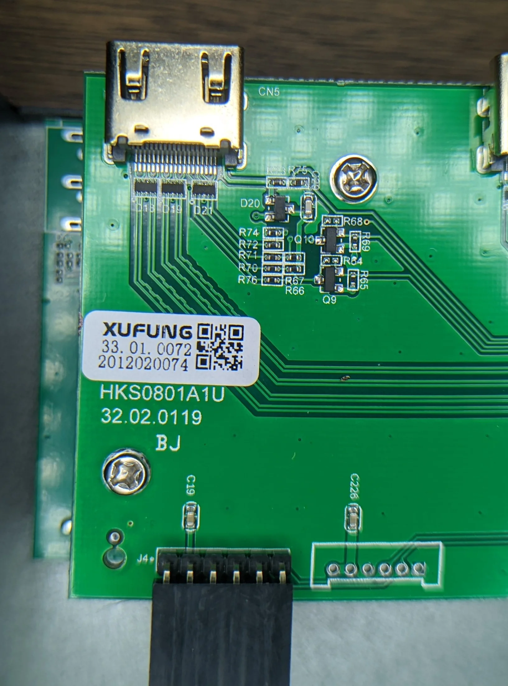
HDMI
In addition to the HDMI switching duties, the HDMI PCB hosts the UART electronics:
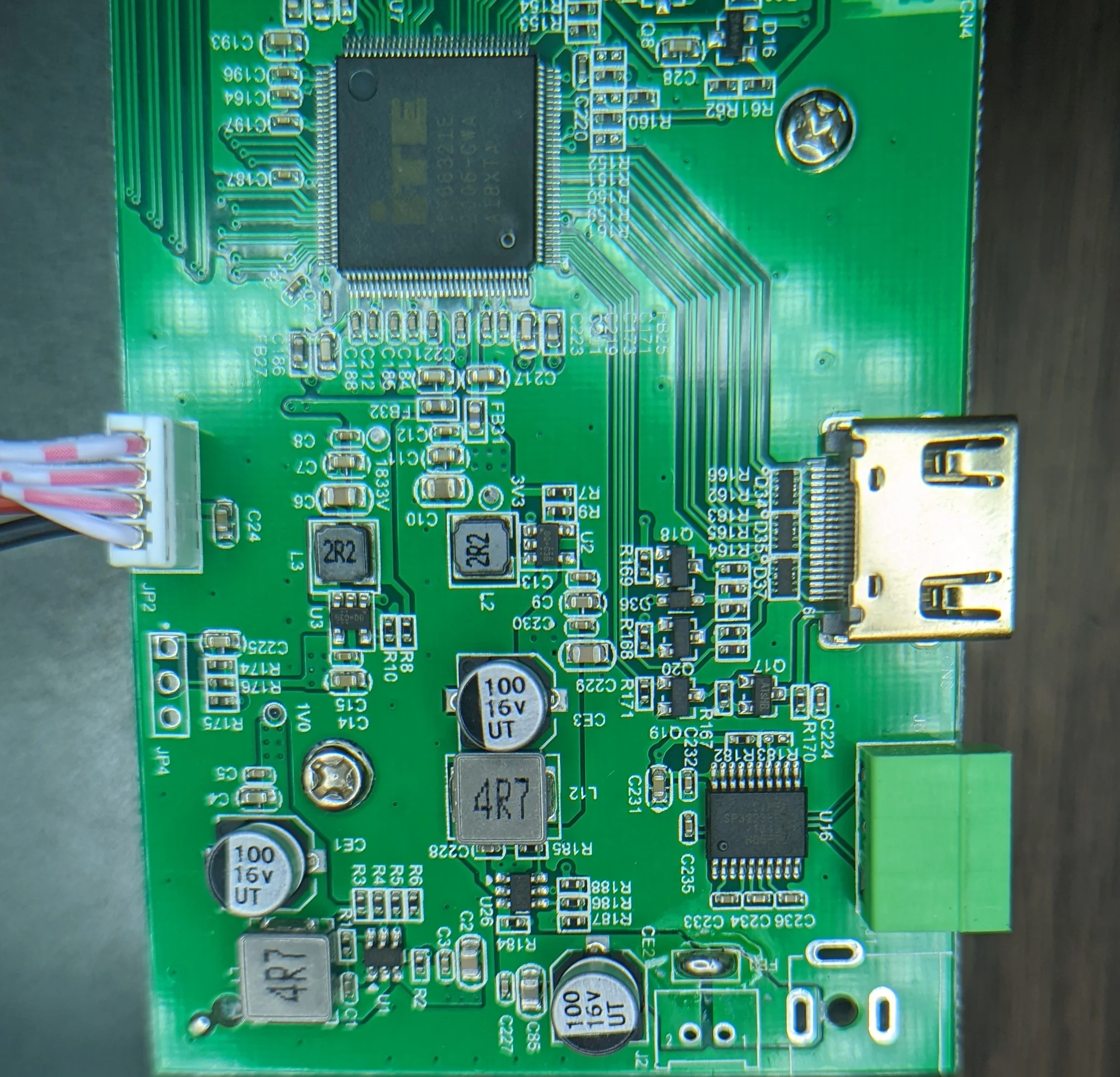
TTL to RS232 handled by the SIPEX SP3223EEX:
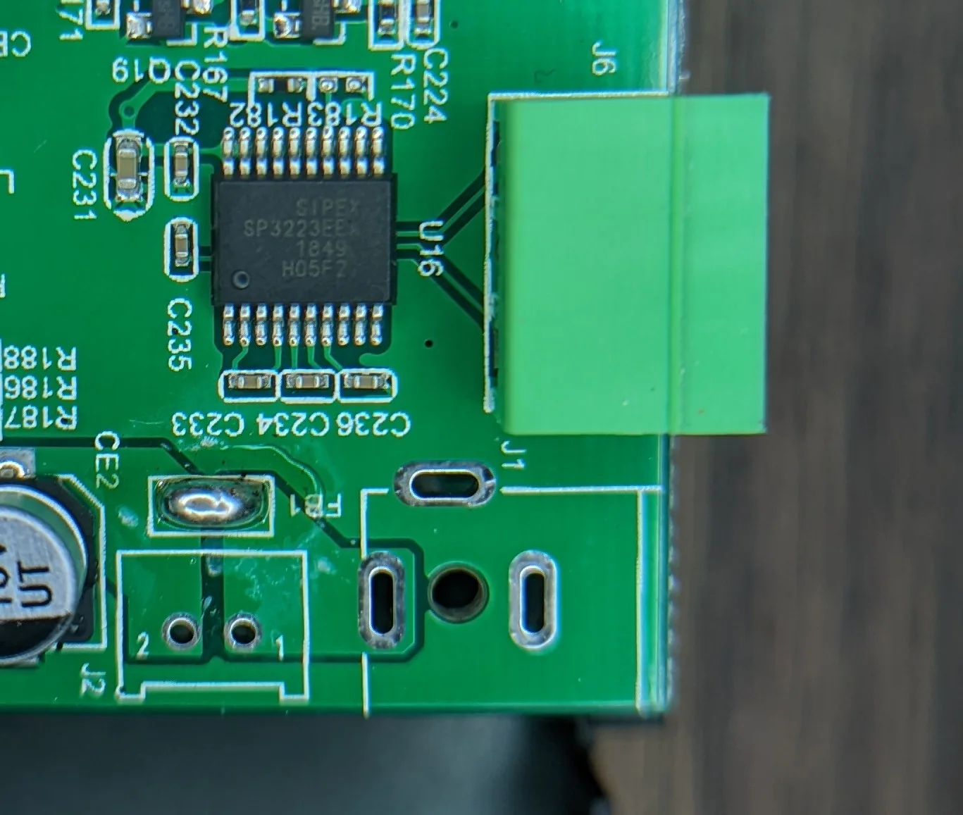
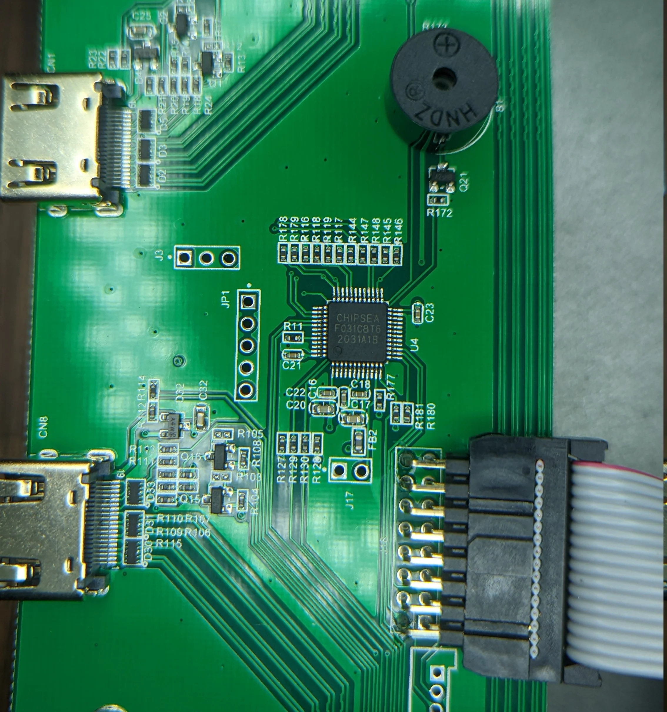
The main application processor appears to be a STM32 clone known as the CHIPSEA F031C8T6.
Switching / routing the HDMI is done with two IT66341TE chips reducing the 4 HDMI inputs down to a single output and a IT66321E to switch between those two streams.
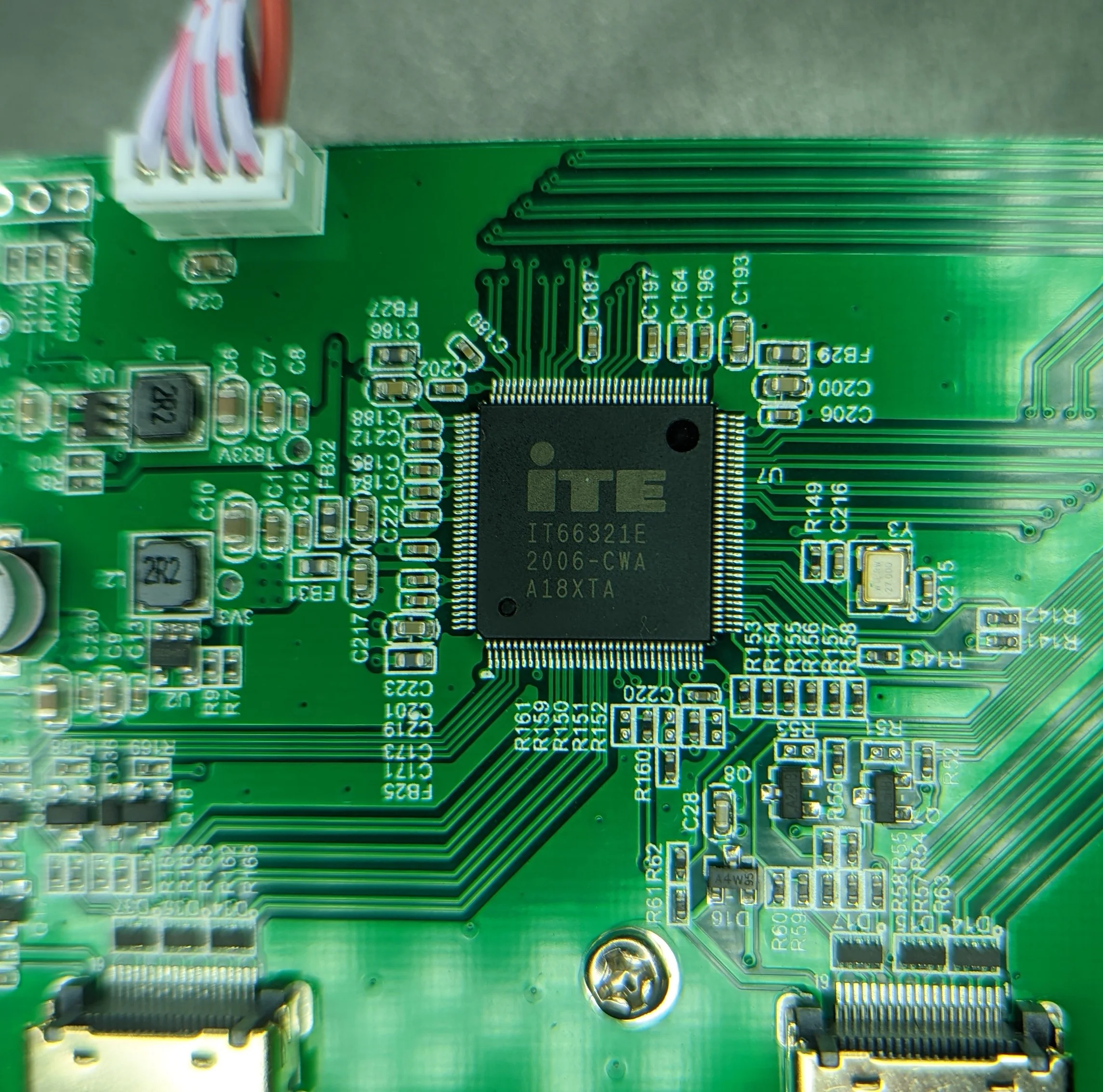
2 to 1 HDMI mux to switch between the two outputs from the 4 -> 1 muxes on board.
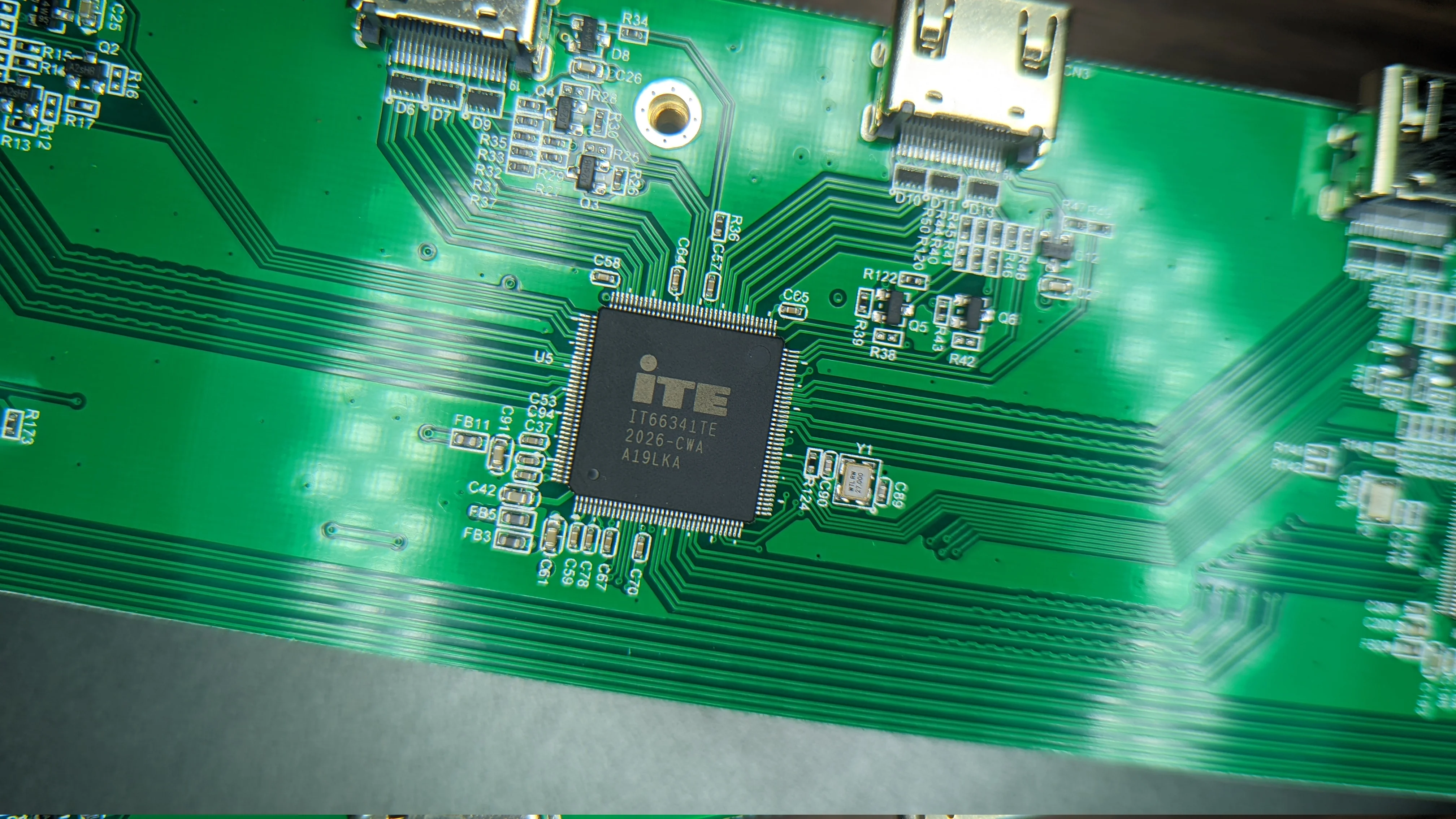
4 to 1 HDMI mux; one of two on the board
I would bet that the unpopulated connector in the bottom right is the bus connection to a second HDMI PCB in the 16 port model but I don’t see where the differential pairs for the HDMI signal would come from so who knows 🤷.
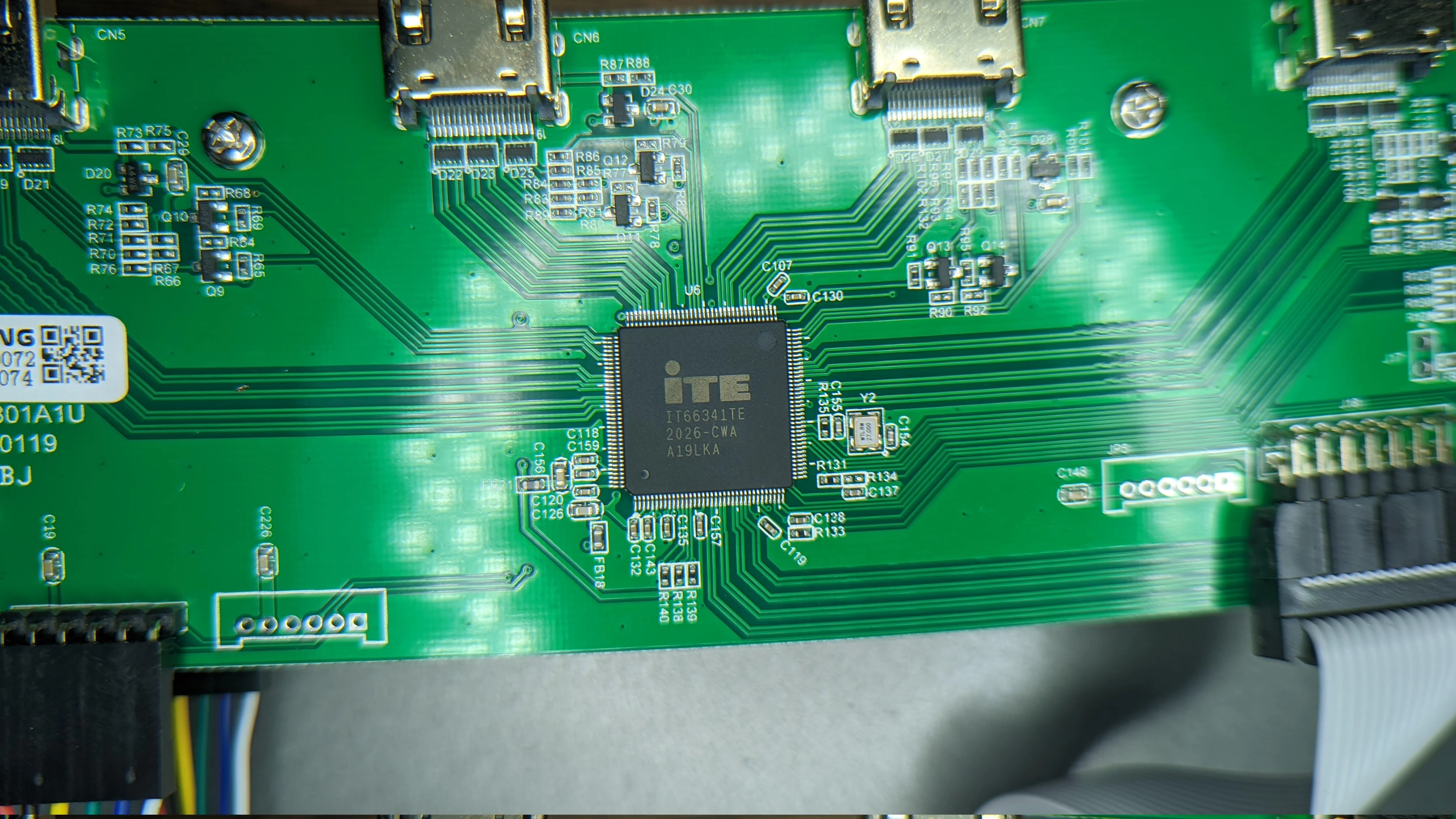
4 to 1 HDMI mux; one of two on the board
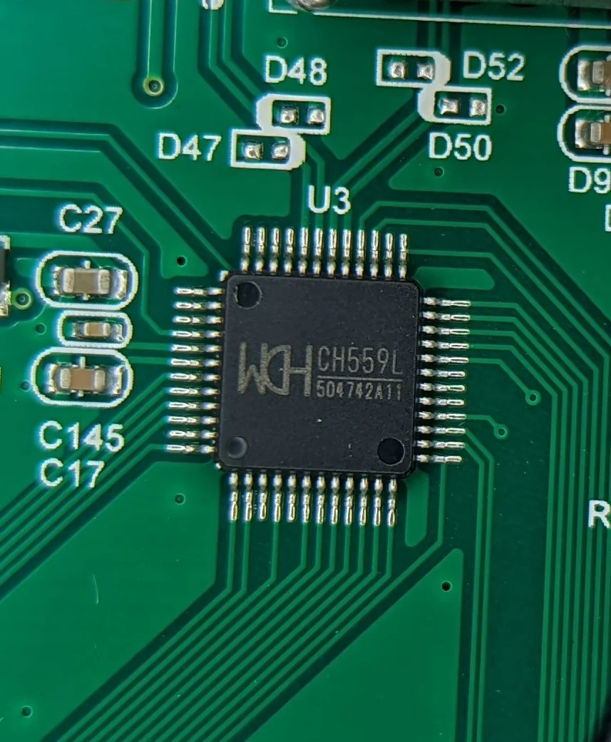
USB
Like the HDMI PCB, the USB PCB uses a series of ASICs and a microprocessor to coordinate them all.
Near the 4 ‘output’ USB ports, you can see the CH559L which runs the show. This IC is monitoring the USB bus for key codes from the keyboard for display switching purposes; press some key combination to switch inputs.
This is usually PrtScrn a few times quickly followed by the number of the input bank you wish to switch to.
I have not tested / verified this functionality but the seller does advertise that there is similar functionality
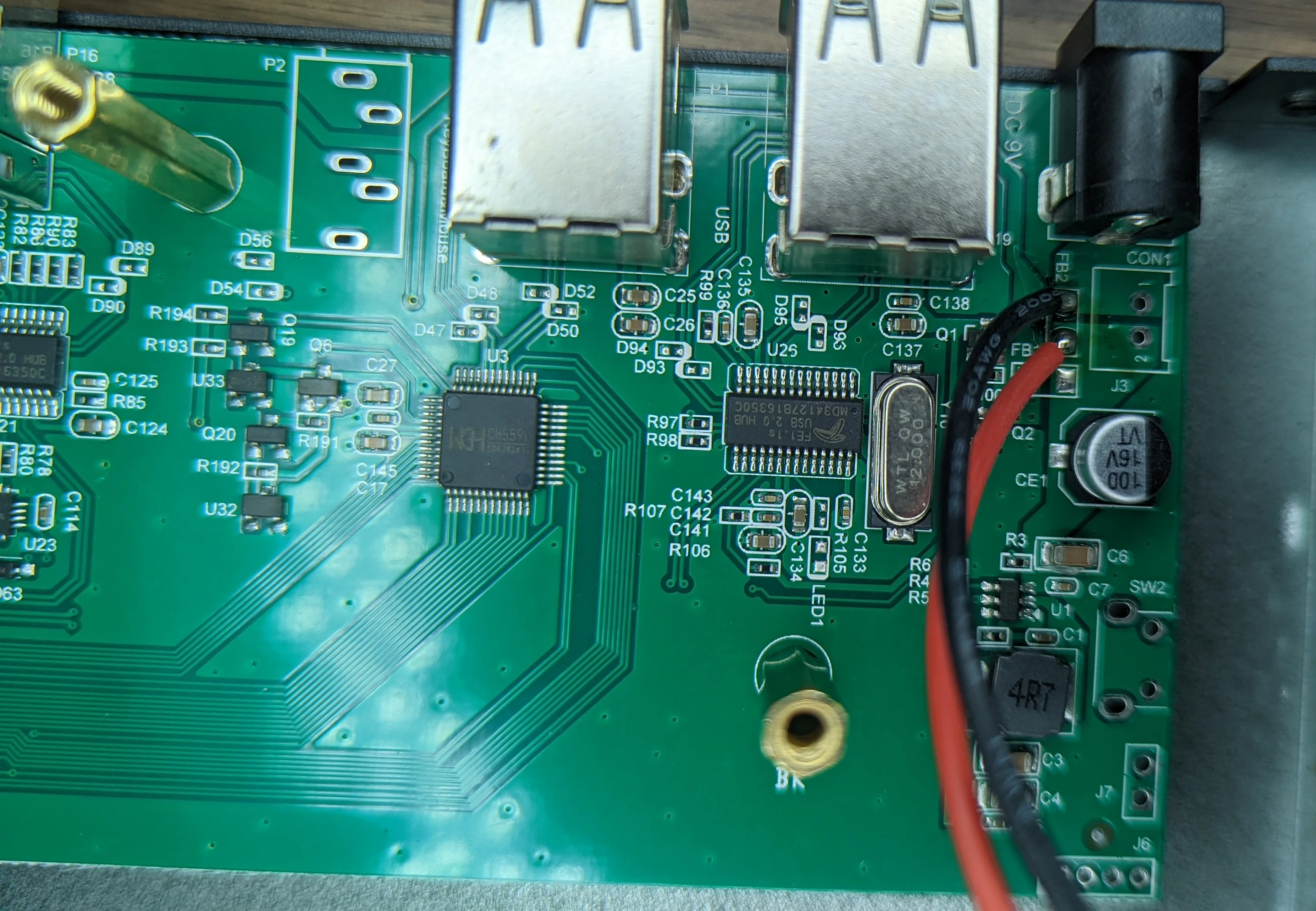
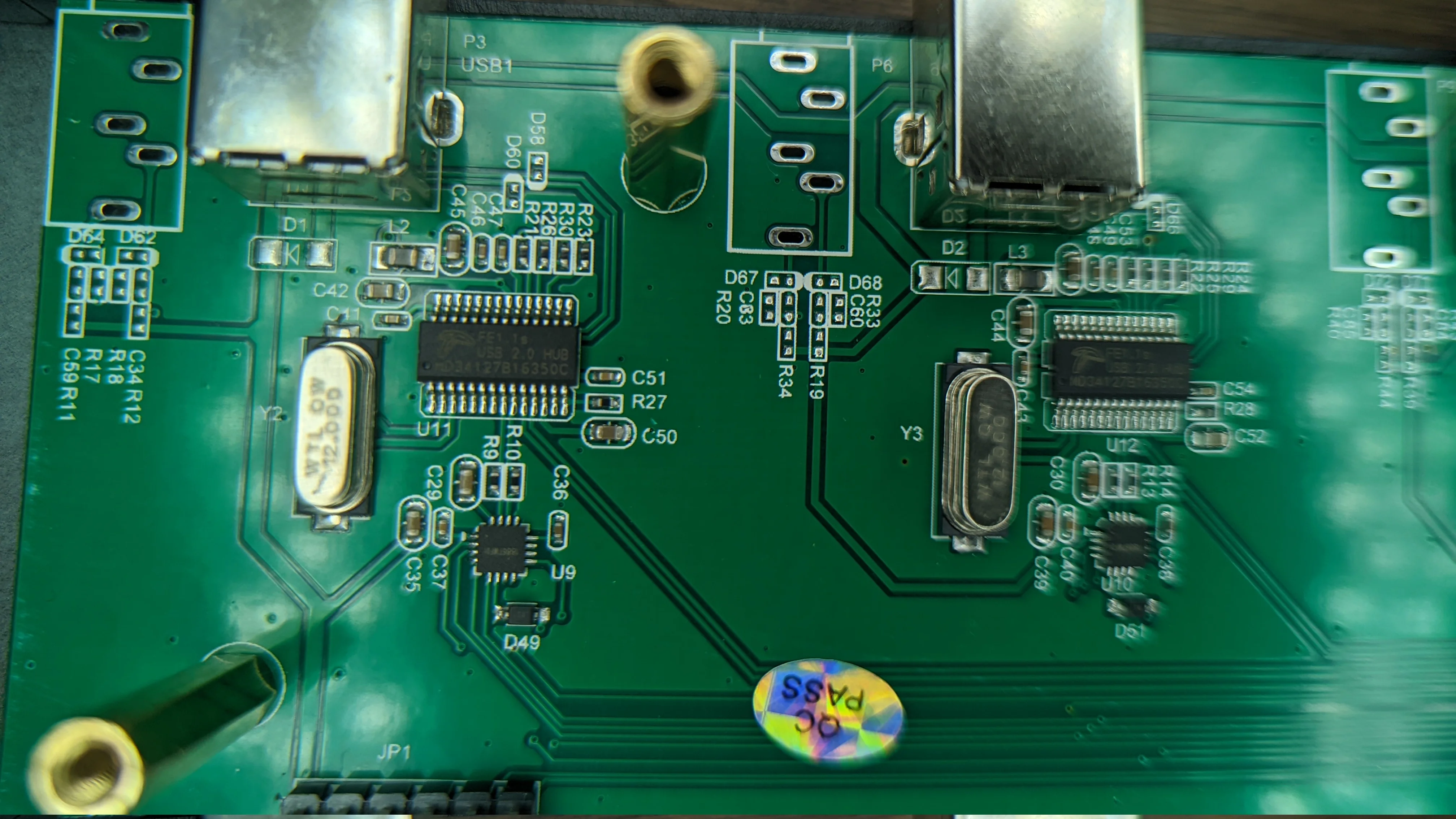
Each ‘input’ USB port is the same: unpopulated headphone jack footprint for audio input and a FE1.1s USB 2.0 HUB ASIC and an unknown IC that looks like it’s related to the unpopulated headphone jack.
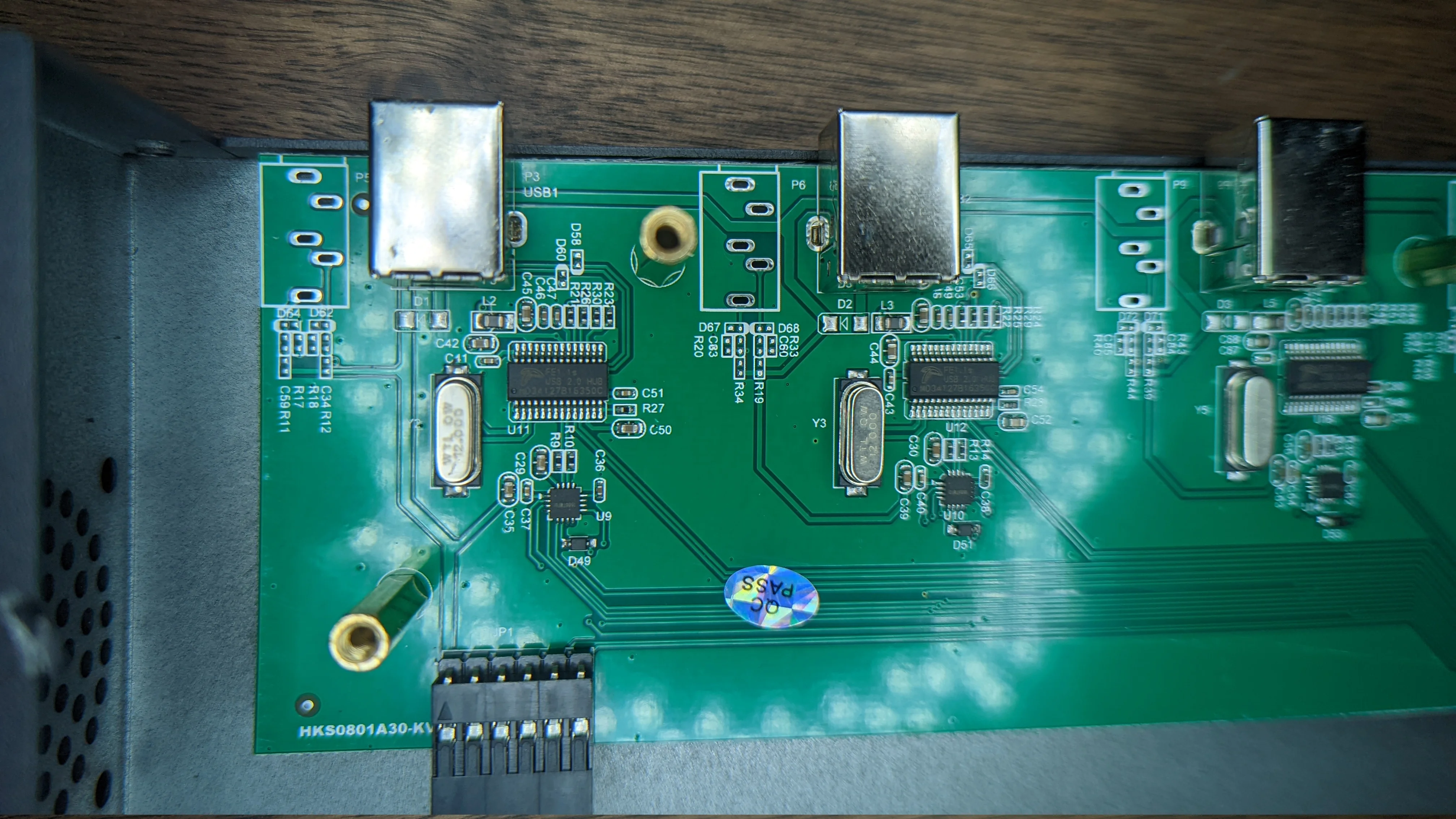
Each 'input' USB port is managed with the same IC. Note the unpopulated Headphone jack footprint on the PCB
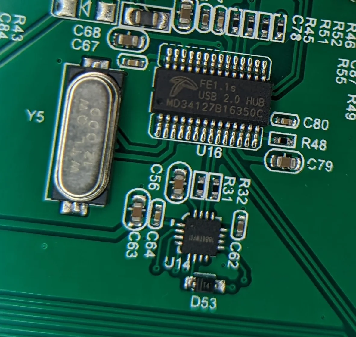
I can't make out the markings, but the 16 pin square IC is almost certainly an audio ID for the unpopulated headphone jack.
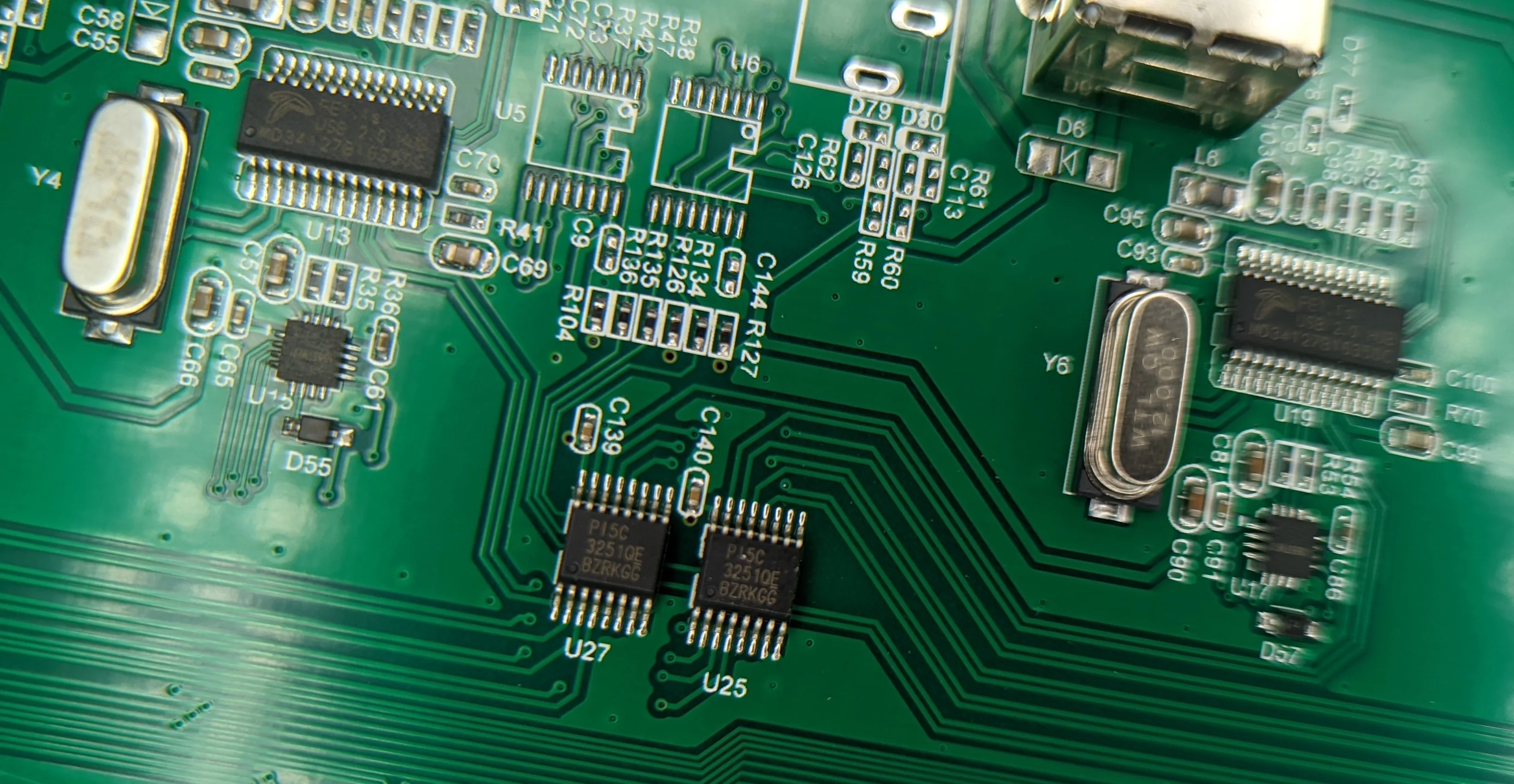
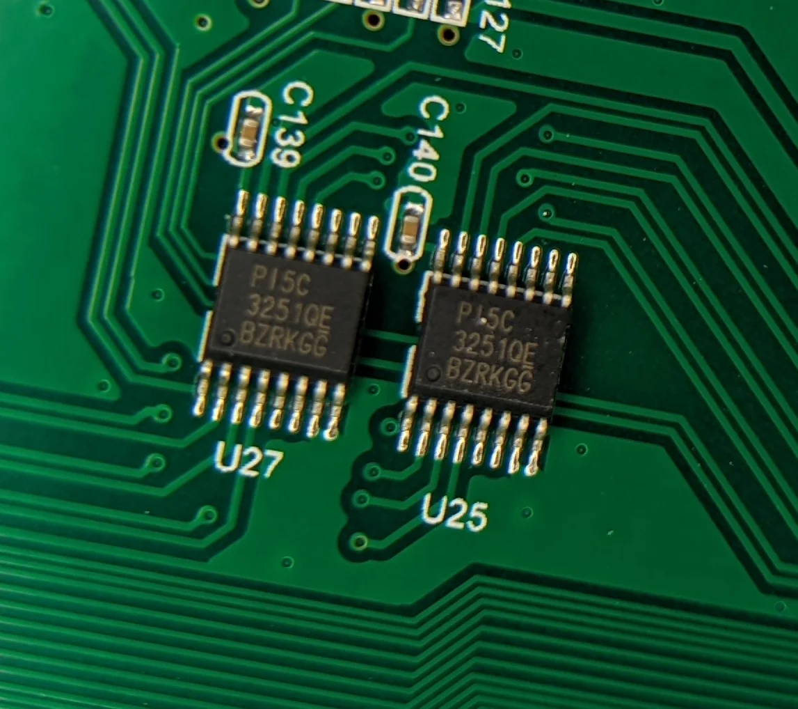
There’s some generic 8:1 GPIO mux chips in the form of 3251QE.
They are simple IO expanders that would allow a microcontroller to read/write 8 GPIO pins using just 3 GPIO.
I don’t know why they’re here or why an 8 port switch needs 2 of them… both on the USB PCB.
That’s it for teardown!
dmesg
Just for completeness, here is how the KVM presents to the computer via USB.
[183000.909155] usb 1-6: new high-speed USB device number 63 using xhci_hcd
[183001.050545] usb 1-6: New USB device found, idVendor=1a40, idProduct=0101, bcdDevice= 1.11
[183001.050550] usb 1-6: New USB device strings: Mfr=0, Product=1, SerialNumber=0
[183001.050551] usb 1-6: Product: USB 2.0 Hub
[183001.112333] hub 1-6:1.0: USB hub found
[183001.112549] hub 1-6:1.0: 4 ports detected
[183001.495837] usb 1-6.1: new high-speed USB device number 64 using xhci_hcd
[183001.687327] usb 1-6.1: New USB device found, idVendor=1a40, idProduct=0101, bcdDevice= 1.11
[183001.687332] usb 1-6.1: New USB device strings: Mfr=0, Product=1, SerialNumber=0
[183001.687333] usb 1-6.1: Product: USB 2.0 Hub
[183001.720379] hub 1-6.1:1.0: USB hub found
[183001.720579] hub 1-6.1:1.0: 4 ports detected
[183001.912509] usb 1-6.2: new low-speed USB device number 65 using xhci_hcd
[183002.137295] usb 1-6.2: New USB device found, idVendor=0c45, idProduct=7403, bcdDevice= 0.01
[183002.137300] usb 1-6.2: New USB device strings: Mfr=1, Product=2, SerialNumber=0
[183002.137301] usb 1-6.2: Product: USB Device
[183002.137303] usb 1-6.2: Manufacturer: SONiX
[183002.239461] input: SONiX USB Device as /devices/pci0000:00/0000:00:01.2/0000:02:00.0/0000:03:08.0/0000:05:00.1/usb1/1-6/1-6.2/1-6.2:1.0/0003:0C45:7403.00E4/input/input288
[183002.296065] hid-generic 0003:0C45:7403.00E4: input,hidraw9: USB HID v1.00 Keyboard [SONiX USB Device] on usb-0000:05:00.1-6.2/input0
[183002.302457] input: SONiX USB Device Mouse as /devices/pci0000:00/0000:00:01.2/0000:02:00.0/0000:03:08.0/0000:05:00.1/usb1/1-6/1-6.2/1-6.2:1.1/0003:0C45:7403.00E5/input/input289
[183002.302535] input: SONiX USB Device System Control as /devices/pci0000:00/0000:00:01.2/0000:02:00.0/0000:03:08.0/0000:05:00.1/usb1/1-6/1-6.2/1-6.2:1.1/0003:0C45:7403.00E5/input/input290
[183002.359252] hid-generic 0003:0C45:7403.00E5: input,hidraw10: USB HID v1.00 Mouse [SONiX USB Device] on usb-0000:05:00.1-6.2/input1
And lsusb shows:
|__ Port 6: Dev 63, If 0, Class=Hub, Driver=hub/4p, 480M
    ID 1a40:0101 Terminus Technology Inc. Hub
    /sys/bus/usb/devices/1-6  /dev/bus/usb/001/063
    |__ Port 2: Dev 65, If 0, Class=Human Interface Device, Driver=usbhid, 1.5M
        ID 0c45:7403 Microdia Foot Switch
        /sys/bus/usb/devices/1-6.2  /dev/bus/usb/001/065
    |__ Port 2: Dev 65, If 1, Class=Human Interface Device, Driver=usbhid, 1.5M
        ID 0c45:7403 Microdia Foot Switch
        /sys/bus/usb/devices/1-6.2  /dev/bus/usb/001/065
    |__ Port 1: Dev 64, If 0, Class=Hub, Driver=hub/4p, 480M
        ID 1a40:0101 Terminus Technology Inc. Hub
        /sys/bus/usb/devices/1-6.1  /dev/bus/usb/001/064
The Microdia Foot Switch bit is odd.
Could that have something to do with the 3251QE muxes?
Perhaps this device indicates to the computer weather or not it is the activated one? 🤔 But why would you need two?
I did not dump EDID information for the HDMI but I suspect that the switch is smart enough to just copy exactly what the display provides so the computers don’t ‘see’ the loss/change of a display which might re-arrange windows or adjust scaling.
ESPHome component
kquinsland/hdmi-kvm-esphome.Yes, I wanted to be able to control this KVM from my Home Assistant install. Some sort of API was a strong desire/requirement for KVM switches for a reason!
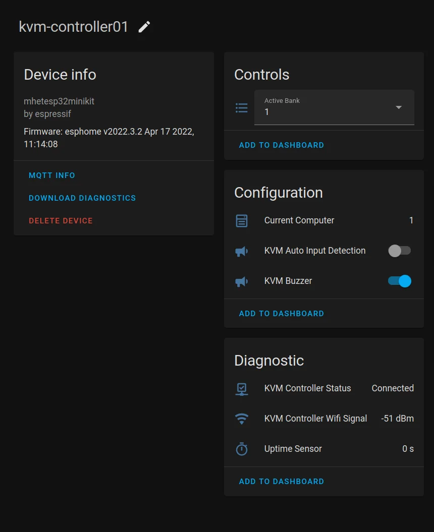
I am still working on a complementary ESPHome component to automate my standing desk (to be published soon!) but to give you an idea of the automations this KVM will be used in:
Push a single button to:
- Turn on the VR computer
- Switch KVM to the VR computer
- Adjust the lighting as needed; turn most lights off as they’re not needed with a VR headset on but turn on ambient lighting so the room isn’t pitch dark when the headset is removed.
When personal/work computer are not in use, switch to a host running Grafana dashboards on rotation
Allow me to track how much time per week is spent with each host
ICs and distinguishing markings
The front panel PCB is labeled: 20170622 and features:
8S003F3P6- A cheapish 8 bit micro controller.
The LAN module PCB is marked with 20151030 and features:\
The HDMI PCB is populated with:
CHIPSEA F031C8T6- STM32 clone; likely the main applications processor. I can’t find a datasheet on this specific on the english speaking web but the naming is oddly similar to how some STM32 processors are named.SIPEX SP3223EEX- Basic TTL <-> RS232 chip, similar to MAX232.IT66321E- 2 IN to 1 OUT HDMI2.0 18Gb/s Switch with Audio In/OutIT66341TE- 4 IN to 1 OUT HDMI2.0 18Gb/s Switch with Audio In/OutA sticker with the markings:
XUFUNG 33.01.0072 2012020074
The PCB is marked with:
HK20801AU 32.02.0119 BJ
The USB PCB is marked with HK20801A30-KVM and is populated with:
PI5C 3251QE- 8:1 Mux/DeMux BusSwitchCH559L- 8 bit enhanced USB MCU CH559FE1.1s- FE1.1S USB 2.0 HIGH SPEED 4-PORT HUB CONTROLLER