Quick and dirty hack to extend the MK3S print area.
This isn’t going to be a long post. I’m working on a larger project but hit a snag and I didn’t find any easy/obvious solutions online so I thought I’d share what I came up with.
Details will come later when the bigger project is ready to be released so you’ll have to forgive me for the lack of context. Essentially I have a large / multi-hour print that almost fits on my MK3s print bed but is too large to slice as is.
Here’s the short version:
- The MK3S has a print area of 250mm x 210mm x 210mm (X, Y, Z).
- The part in question is circular and has a circumference of ~215mm so I need to extend the Y axis by ~5mm.
- I can’t scale it down to fit as it’s a functional part with specific dimensions.
The problem
PrusaSlicer refuses to slice the part and gives the following error message:
“An object outside the print area was detected. Resolve the current problem to continue slicing.
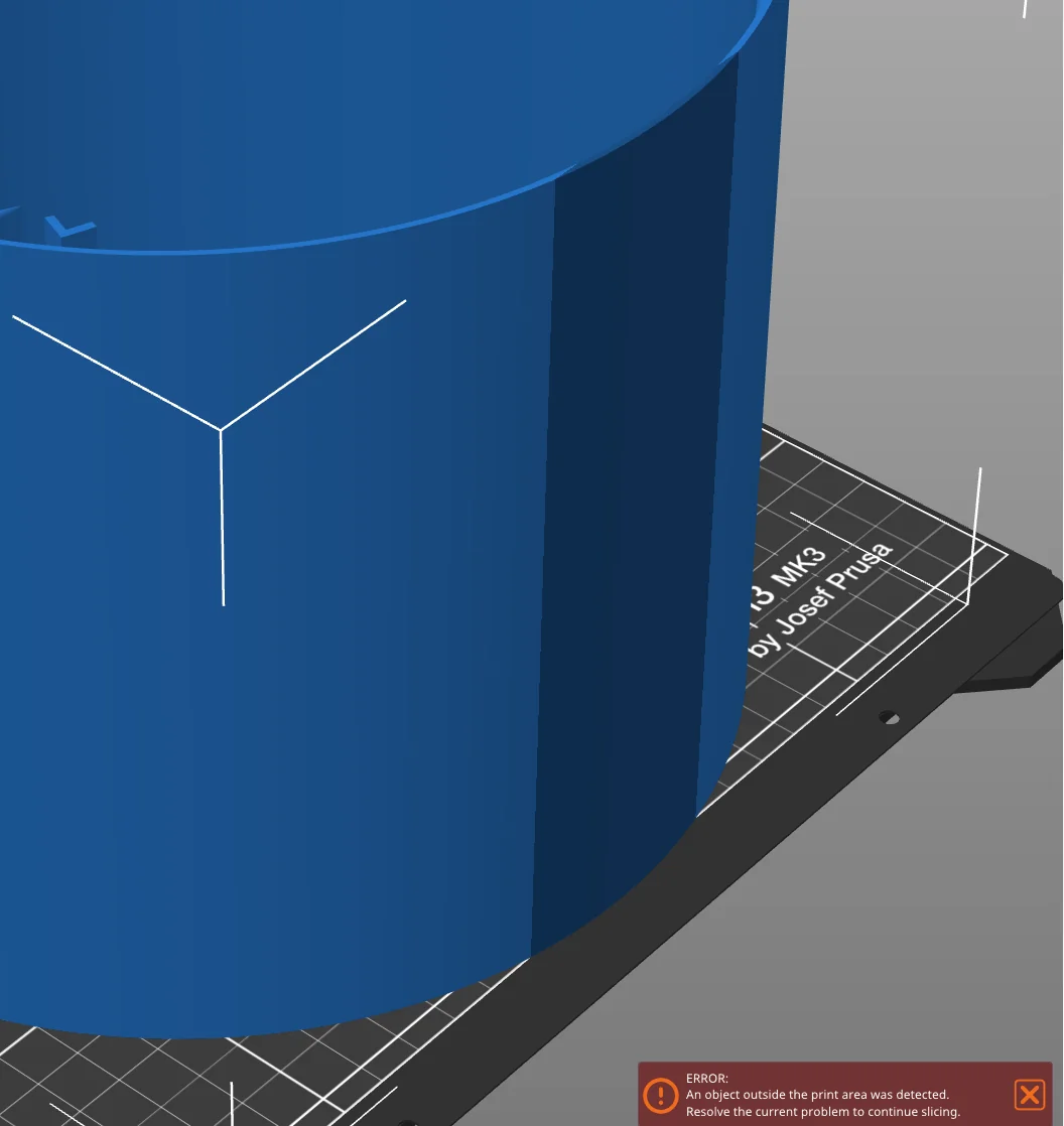
The part JUST BARELY fits on the print bed. This whole trick only works because the dark blue portion is so small.
Since the part is circular, there’s no way to “rotate” it to fit within the print area.
The “idea”
In the image above, the dark blue portion of the part is “outside” the print area; some portion of the object is below the 0,0 origin of the print bed.
But the pre-print priming line is done further “south” on the build plate so we know the printer can physically print in the area; it’s only a software limitation preventing it from doing so.
This can be confirmed by looking at “stock” gcode:
<...>
; Prime line routine
G0 Z0.15 ; Restore nozzle position - (thanks tim.m30)
M900 K0; Disable Linear Advance for prime line
G92 E0.0 ; reset extrusion distance
G1 Y-3.0 F1000.0 ; go outside print area
<...>
The G1 line shown above moves the print head to -3.0 mm on the Y axis.
Since I only need a few mm of extra space an the printer clearly has a few mm of extra space… 🤔.
Can I “trick” the slicer into generating valid gcode and then modify the gcode to shift the part down by 5mm?
Yep.
It works 😅.
The “fix”
Convince the slicer to generate valid gcode and then modify the gcode to shift the part down by 5mm. To do this:
- Modify the print bed dimensions in PrusaSlicer so the part will fit the print bed w/o any warnings. Don’t make the print bed any larger than needed and do not make it any larger than the printer is physically capable of.
- Slice as usual, save the
gcodeto a file. - Run the script below which will shift every print instruction by 5mm in the Y direction.
- Send the modified
gcodeto the printer and hope for the best 🤞.
Graphically, it looks like this:
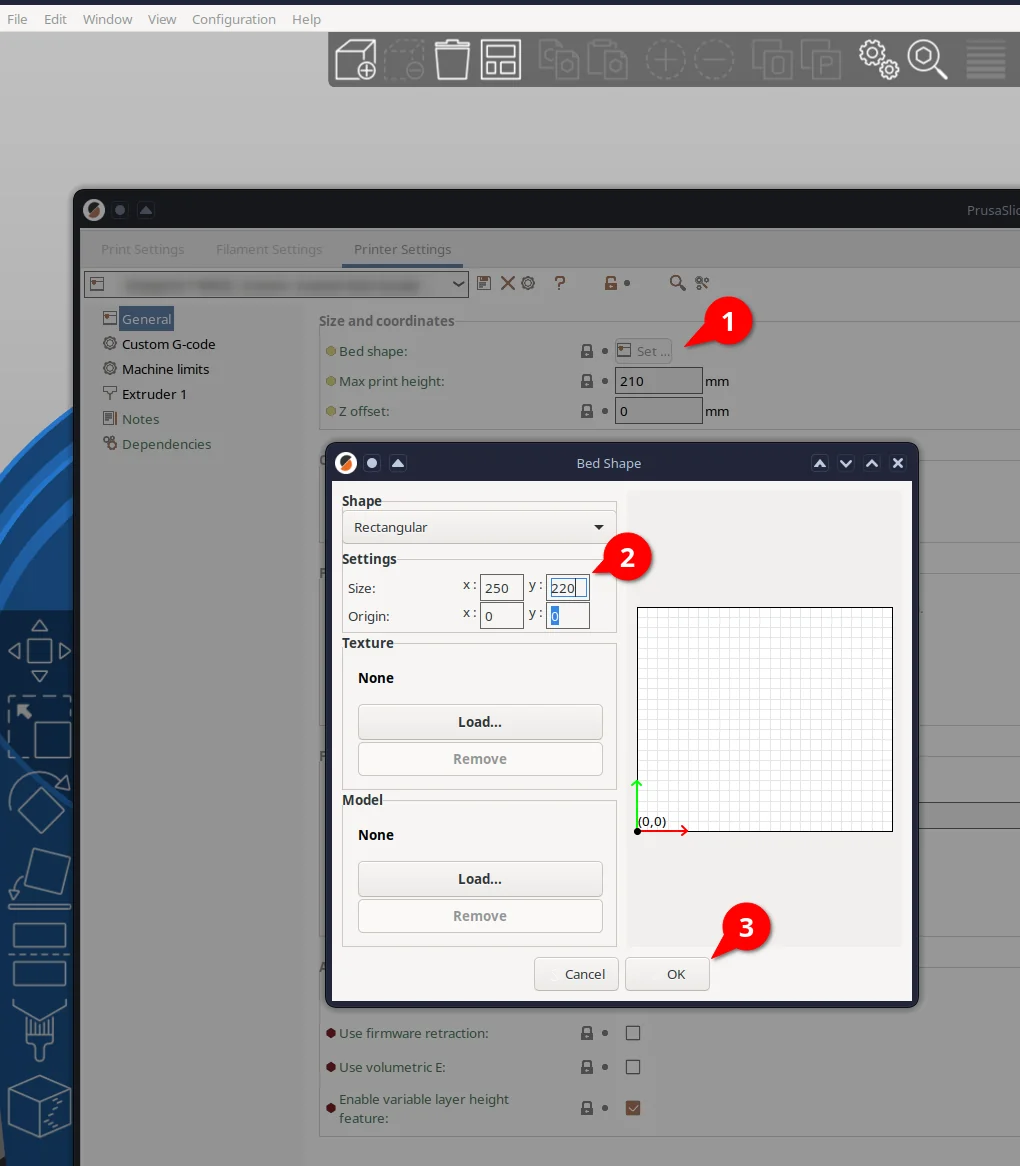
After saving the adjusted print bed dimensions, the part should fit and slice without any warnings.
The code
It’s not pretty but it works.
def adjust_gcode_y_position(input_file, output_file, adjustment):
    with open(input_file, 'r') as infile, open(output_file, 'w') as outfile:
        for line in infile:
            if 'Y' in line and ('G0' in line or 'G1' in line):
                # Split the line into components to find the Y component
                parts = line.split()
                new_parts = []
                for part in parts:
                    if part.startswith('Y'):
                        # Extract current Y value and adjust
                        y_value = float(part[1:]) - adjustment
                        new_parts.append('Y{:.3f}'.format(y_value))
                    else:
                        new_parts.append(part)
                # Write the adjusted line
                outfile.write(' '.join(new_parts) + '\n')
            else:
                # Write unmodified line
                outfile.write(line)

# Usage
input_gcode_path = 'your_original_gcode_file_here.gcode'
output_gcode_path = 'ADJ.your_original_gcode_file_here.gcode'
y_adjustment = 5.0

adjust_gcode_y_position(input_gcode_path, output_gcode_path, y_adjustment)
The result
See for yourself:
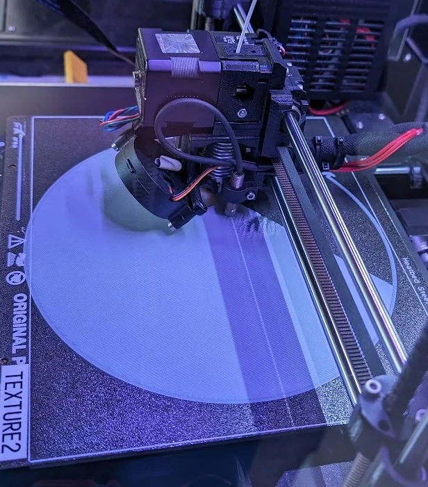
Ignore the wrinkles just to the right of the PINDA probe; it's a separate issue.
Note that the edge of the circle just barely touches the edge of the print bed on the right and “sits” a few mm below the “usable” print bed area on the left.
Hopefully that’s helpful to someone else out there. If anybody knows why Prusa “reserves” this space, I’d love to know.