ESPHome for Sinilink PC remotes
PC (power) remote control
While doing research for a potential project, I stumbled onto a device that fit’s so squarely into that “it’s so simple and obvious, why didn’t I think tof that?!” category that I immediately placed an order for a few.
That device?
A simple WiFi equipped micro controller that gets wired between the power button on a PC and the motherboard. This makes it possible to remotely control and monitor the power state of any PC!
I am using these devices in conjunction with my previously integrated KVM switch to automate turning hosts on/off as they are activated/deactivated on the KVM switch.
There are several different types of device on Ali Express. Most appear to use TuYa MCUs so it’s not immediately clear if/how those devices can be converted to use ESPHome or not; buy those at your own risk.
The two Sinilink devices liked below are trivial to get working with ESPHome/Tasmota though!
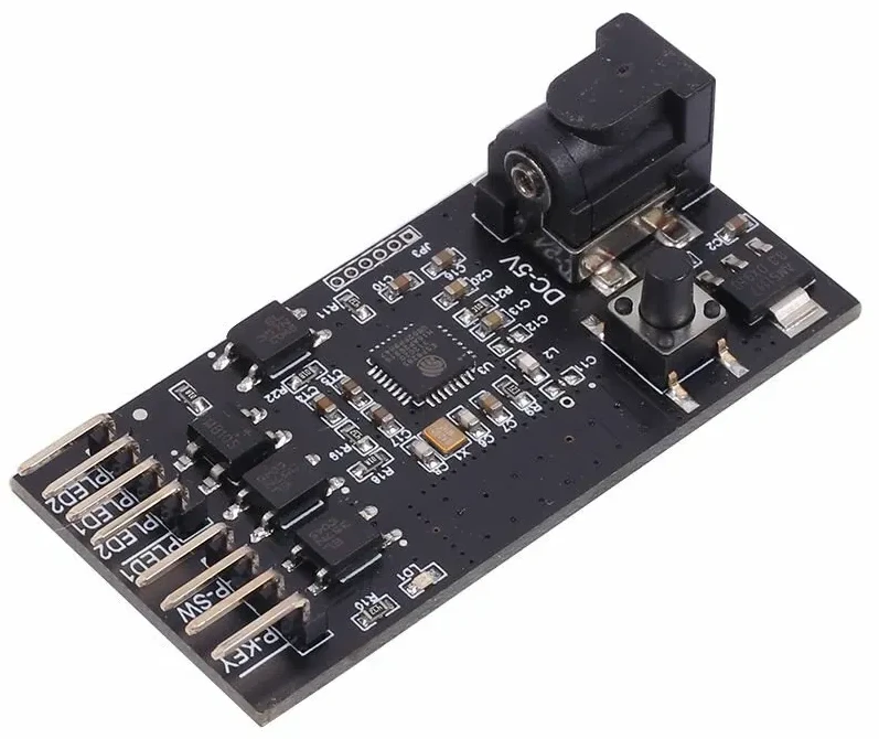
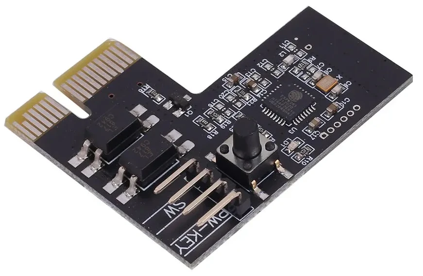
The PCI Express version is simpler to integrate with a PC as it uses the 3.3v power rails to determine when the PC is on. The USB version does not have this luxury so power must be supplied via the DC barrel jack. Additionally, the USB version is also wired series with the power LED(s) on the computer so the module can discern the PCs power state.
Yes, Home Assistant does have support for Wake On Lan but I chose not to use it for a few reasons:
Does not work across subnets. WoL uses a broadcast packet and routers tend to frown on forwarding those between subnets. As my HA instance runs inside of Kubernetes, it’s going to be more than a little difficult to get the WoL packets out of the cluster!
Does not do status checking. The Sinilink modules have direct feedback about the state of the PC power.
Does not do shutdown. There is no WoL packet that can send a PC back to sleep!
If you use the PCI Express version and find that the module does not stay powered up while the PC is asleep/off, check your PC BIOS for ErP settings.
I had to explicitly turn off ErP and permit the PC to wake from PCI-E devices before the 3.3v standby rail was activated.
A quick detour about write_flash errors
I don’t see this error often but I do see it enough to warrant talking about.
I ordered 3 of the PCI Express and the USB version of the devices above. Of the 6 devices I received, 3 didn’t “take” the custom firmware.
Devices that have defects with the onboard flash will appear to be function when probed with esptool.py but will exhibit some sort of error when doing any write_flash operations.
The symptoms present like this
# Note the baud rate; it's considerably slower than the default baud rate.
# Trying lower baud rates is a suggested 'fix'.
❯ esptool.py -b 19200 --port /dev/ttyUSB0 write_flash -fs 1MB -fm dout 0x0 ~/Downloads/tasmota-lite.bin
esptool.py v3.3.1
Serial port /dev/ttyUSB0
Connecting...................
Detecting chip type... Unsupported detection protocol, switching and trying again...
Connecting...
Detecting chip type... ESP8266
Chip is ESP8285H16
Features: WiFi, Embedded Flash
Crystal is 26MHz
MAC: e8:aa:bb:cc:dd:ee
Uploading stub...
Running stub...
Stub running...
Configuring flash size...
Flash will be erased from 0x00000000 to 0x0007afff...
Compressed 501328 bytes to 358200...
Wrote 501328 bytes (358200 compressed) at 0x00000000 in 188.8 seconds (effective 21.2 kbit/s)...
File  md5: 693ff98fbada203ab23ced0650e45ab7
Flash md5: 2a3e7abaf93800f4193d03a9da8c52fa
MD5 of 0xFF is 36d49993e146cee00d35f8793084f71c

A fatal error occurred: MD5 of file does not match data in flash!
and
❯ esptool.py --port /dev/ttyUSB0 write_flash -fs 1MB -fm dout 0x0 ~/Downloads/tasmota-lite.bin
esptool.py v3.3.1
Serial port /dev/ttyUSB0
Connecting...
Detecting chip type... Unsupported detection protocol, switching and trying again...
Connecting...
Detecting chip type... ESP8266
Chip is ESP8285H16
Features: WiFi, Embedded Flash
Crystal is 26MHz
MAC: e8:aa:bb:cc:dd:ee
Stub is already running. No upload is necessary.
Configuring flash size...
Flash will be erased from 0x00000000 to 0x0007afff...
Compressed 501328 bytes to 358200...
Writing at 0x00075960... (100 %)
A fatal error occurred: Serial data stream stopped: Possible serial noise or corruption.
There are a few “fixes” for this issue but none worked for me:
- Check for loose or fault connections.
- Use a robust power supply
- Try
write_flash_statuswith--non-volatile 0 - Try a different USB <-> 232/TTL adapter
I tried all of the above and nothing worked.
- I soldered wires directly to the modules instead of just inserting pins into the programming header.
- I tried a power supply that can supply considerably more than the ~200 ma needed to power/flash the chip.
- I tried a few different USB ports and a few different USB <-> TTL adapters with both counterfeit and authentic FTDI chips.
- I used
read_flash_statusand saw that the--non-volatilesettings were already0x0000.
None of the above worked for me.
While disappointing and frustrating, there’s only one probable conclusion: there’s a subtle defect in the flash memory that either wasn’t noticed or checked for at the factory when the OEM firmware was flashed onto the devices.
I cut my losses and moved on.
ESPHome configurations
For SEO/Archival purposes, I have also uploaded a copy of the config to the esphome-devices.com site.
As of publishing this article, the PR is pending review.
If/When the page goes live, I’ll update the link here.
The configurations there are bare-bones and cover just the basics required to get the GPIO working with ESPhome.
The configuration below is a bit more featured and is a lot closer to the versions that I use in production. It features a “pc power button lockout” feature and more.
packages: heading are “standard” across all of my ESPHome configurations and are not included here.
Either remove them or substitute as needed to get something that works for you.substitutions:
# Displayed in HA frontend
friendly_name: "Desktop Power Control"
friendly_name_short: "Desktop"
hostname: "desktop-power-control"
esphome:
name: ${hostname}
# Shows up in UI
comment: "Remote power button for ${friendly_name_short}."
esp8266:
# Specifically a 'ESP8285H16' with 2MB built in flash
# See: https://docs.platformio.org/en/stable/boards/espressif8266/esp8285.html
board: esp8285
logger:
level: INFO
# See: https://esphome.io/guides/configuration-types.html#packages
packages:
# General
wifi: !include ../../packages/wifi.yaml
mqtt: !include ../../packages/mqtt.yaml
time: !include ../../packages/ntp.yaml
ota: !include ../../packages/ota.yaml
web_server: !include ../../packages/web_server.yaml
status_led:
pin:
number: GPIO02
inverted: True
# Keep track of weather or not case button press should be forwarded to the motherboard
globals:
- id: glbl_relay_latched
type: bool
restore_value: no
initial_value: "true"
script:
- id: regular_press
mode: single
then:
- output.turn_on: out_relay
- delay: .5s
- output.turn_off: out_relay
- id: long_press
mode: single
then:
- output.turn_on: out_relay
# MB seems to respond to 5s, add 2 just to be safe
- delay: 7s
- output.turn_off: out_relay
button:
# We expose a button to the HA web UI that mimics the "forceful" power down sequence
- name: "${friendly_name_short} Long Press"
id: btn_forceful_down
platform: template
on_press:
- lambda: |-
// If the power state is off, we'll emit a WARN level message before running the script
if( !id(inp_power_status).state ){
ESP_LOGW("forcefulShutdown", "Power state is OFF but forceful shutdown requested...");
} else {
ESP_LOGW("forcefulShutdown", "Power state is ON. Forceful shutdown requested...");
}
id(long_press).execute();
binary_sensor:
# React to connection status, if needed
- <<: !include ../../packages/binary_sensor/connection_status.config.yaml
- name: "${friendly_name_short} WiFi Config Button"
platform: gpio
id: inp_wifi_cfg_btn
entity_category: "diagnostic"
icon: "mdi:radiobox-marked"
pin:
number: GPIO04
mode: INPUT_PULLUP
inverted: True
- name: "${friendly_name_short} Case Button"
platform: gpio
id: inp_pc_case_btn_status
entity_category: "diagnostic"
icon: "mdi:power-standby"
pin:
number: GPIO10
mode: INPUT_PULLUP
inverted: True
on_press:
then:
- if:
condition:
lambda: 'return id(glbl_relay_latched);'
then:
- output.turn_on: out_relay
else:
- logger.log: "PC Case button press but disarmed!"
on_release:
then:
- if:
condition:
lambda: 'return id(glbl_relay_latched);'
then:
- output.turn_off: out_relay
else:
- logger.log: "PC Case button release but disarmed!"
##
# Press is momentary quick
on_click:
then:
- lambda: |-
// If relay isn't latched, do nothing
if( !id(glbl_relay_latched) ){
ESP_LOGD("caseBtnPress", "button pressed, not latched so doing nothing.");
return;
}
ESP_LOGD("caseBtnPress", "button pressed, latched. Toggling power now...");
id(sw_pc_power).toggle();
on_multi_click:
- timing:
- ON for at most 1s
- OFF for at most 2s
- ON for at most 1s
- OFF for at most 2s
- ON for at most 1s
- OFF for at most 2s
then:
# We'd want to press a virtual / template button for hard power down
# That template button would run a script that just raised the output hight for 10s
- logger.log: "Triple clicked!"
- button.press: btn_forceful_down
- name: "${friendly_name_short} Power Status"
platform: gpio
id: inp_power_status
device_class: "power"
entity_category: "diagnostic"
icon: "mdi:power-settings"
pin:
number: GPIO12
mode: INPUT_PULLUP
inverted: True
switch:
- name: "${friendly_name_short} Relay Latch"
platform: template
id: sw_relay_mode
device_class: "switch"
icon: "mdi:link-variant"
entity_category: "config"
lambda: |-
if (id(glbl_relay_latched)) {
return true;
} else {
return false;
}
turn_on_action:
- globals.set:
id: glbl_relay_latched
value: "true"
turn_off_action:
- globals.set:
id: glbl_relay_latched
value: "false"
- name: "${friendly_name_short} Power"
id: sw_pc_power
platform: template
icon: "mdi:power-plug"
device_class: "switch"
lambda: |-
if (id(inp_power_status).state) {
return true;
} else {
return false;
}
# Mimic the user pressing the button
turn_on_action:
- script.execute: regular_press
turn_off_action:
- script.execute: regular_press
output:
- platform: gpio
id: out_relay
pin: GPIO5