Teardown and Home Assistant integration with two generic Chinese 'smart' power strips.
I love the Sonoff-S31 smart plugs. They’re cheap, well made and - most importantly - trivial to flash with ESPHome and integrate into Home Assistant. They do have one obvious draw back, though; optimized for a “traditional” US style outlet. When you try to deploy them to a power strip, you end up loosing about 50% of the outlets on the strip!
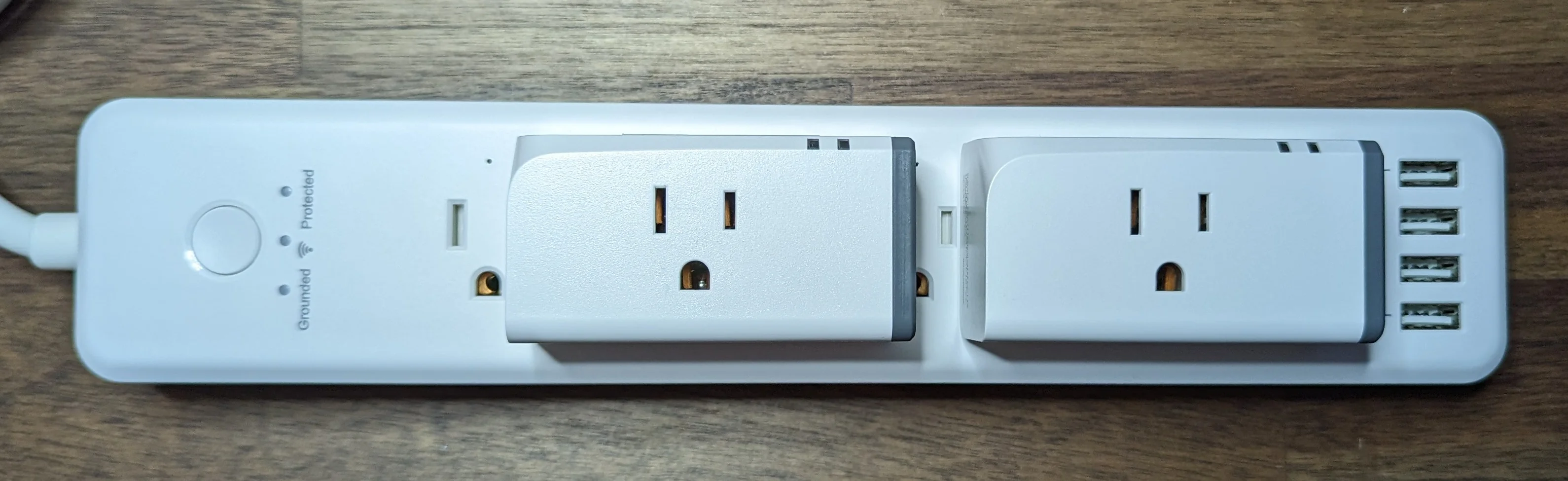
This is how you loose about 50% of the outlets on your power strip.
I figured that there must be a power strip out there that had the WiFi radio, power supply and relays built in.
Looking through the Power Strip listing of the excellent Tasmota device/template repository, there are more than a few options out there.
Upon closer inspection, almost all of them are from super generic/no-name Chinese brands and lack any ETL or UL certifications 😬.
Searching for smart power strips on Amazon returns several results… and only a few from name brands. The few name brand power strips out there that I could find are using their own microcontrollers internally and are immediately disqualified as they’ll be - at best - difficult ot integrate with Home Assistant.
I’m not quite so concerned about any power conditioning/surge suppression as I am not plugging in any valuable or delectate electronics. I am concerned with a more integrated / space efficient solution that allows me to retain my ESPHome/Home Assistant integration.
After cross referencing the Tasmota templates listing with the Amazon search listings, it became clear that there’s really only a few designs that get sold under several different brands and that virtually all of the devices that were known to be powered by an ESP micro are no longer for sale on Amazon.
I eventually took a gamble on two:
BN-Link
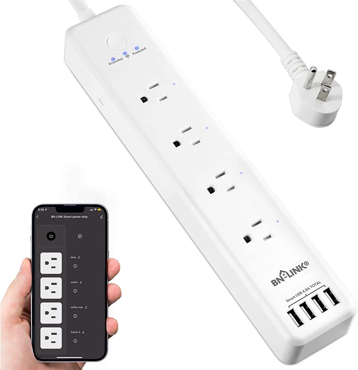
Marketing photo for the BN-Link power strip
This opens up with a standard philips screw driver and you only need one bit size for all screws - nice touch!
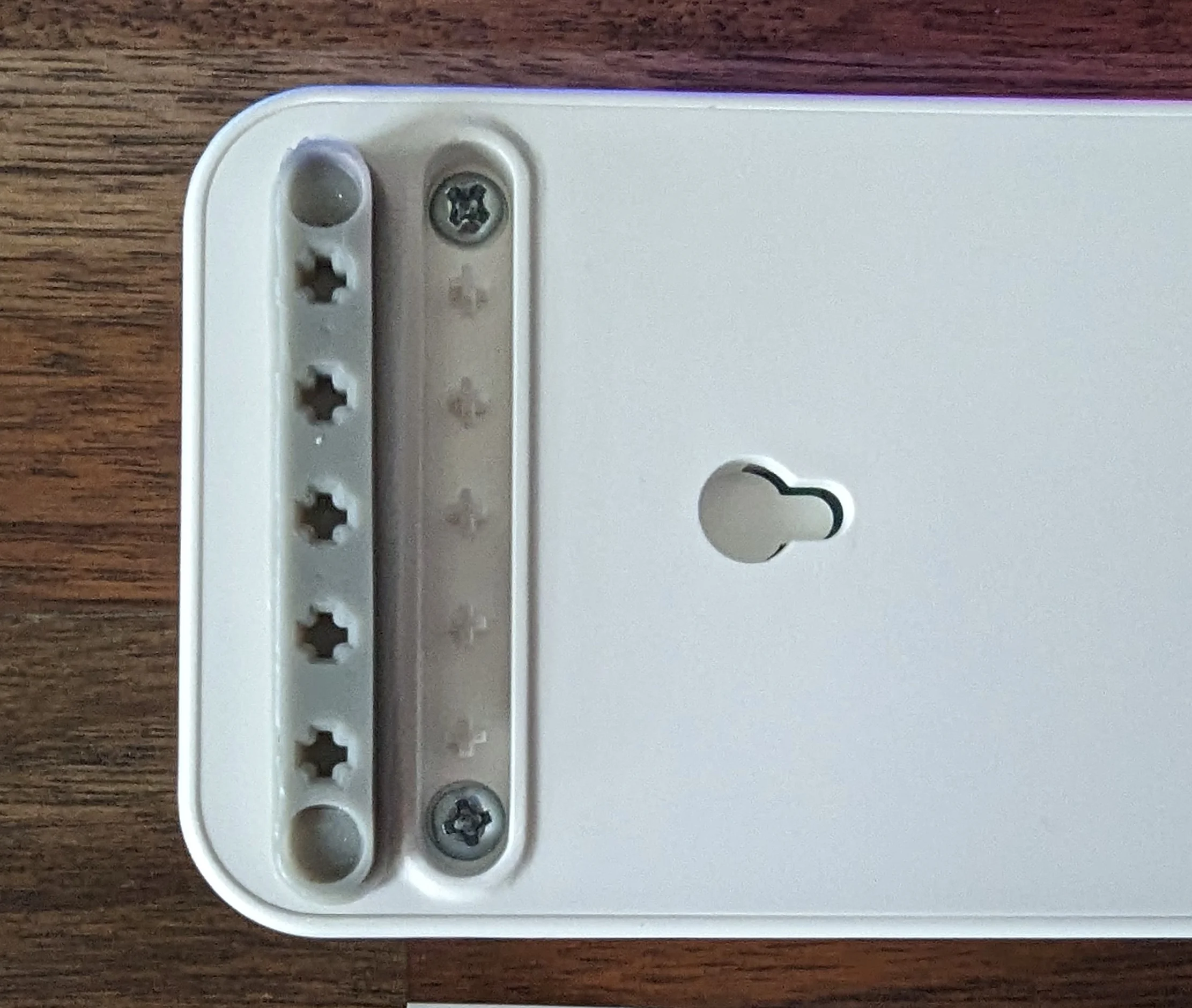
The screws are hiding under the anti-slip pads but instead of those being glued down, the pads use a friction fit on the + shaped locating pegs.
I really like this design feature as the glued pads never stick quite as well when replaced.
In addition to the 4 screws, there are several plastic clip/tabs around the permitter that take some work to carefully undo.
If you have a thin metal pry tool / spudger, it will come in handy!
Overall, the physical construction is solid enough and - pleasantly - serviceable.
I'm not loving the sloppy wiring connecting the USB power supply to the mains rails.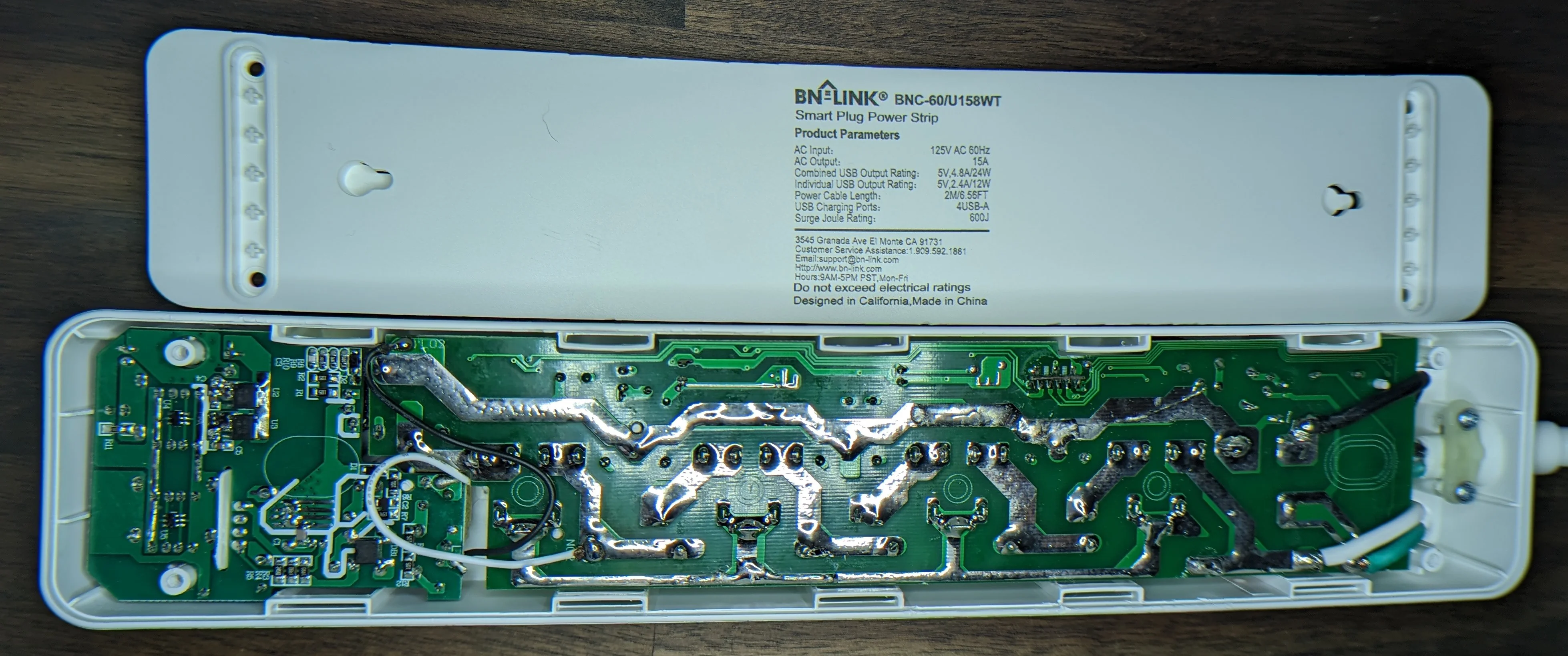
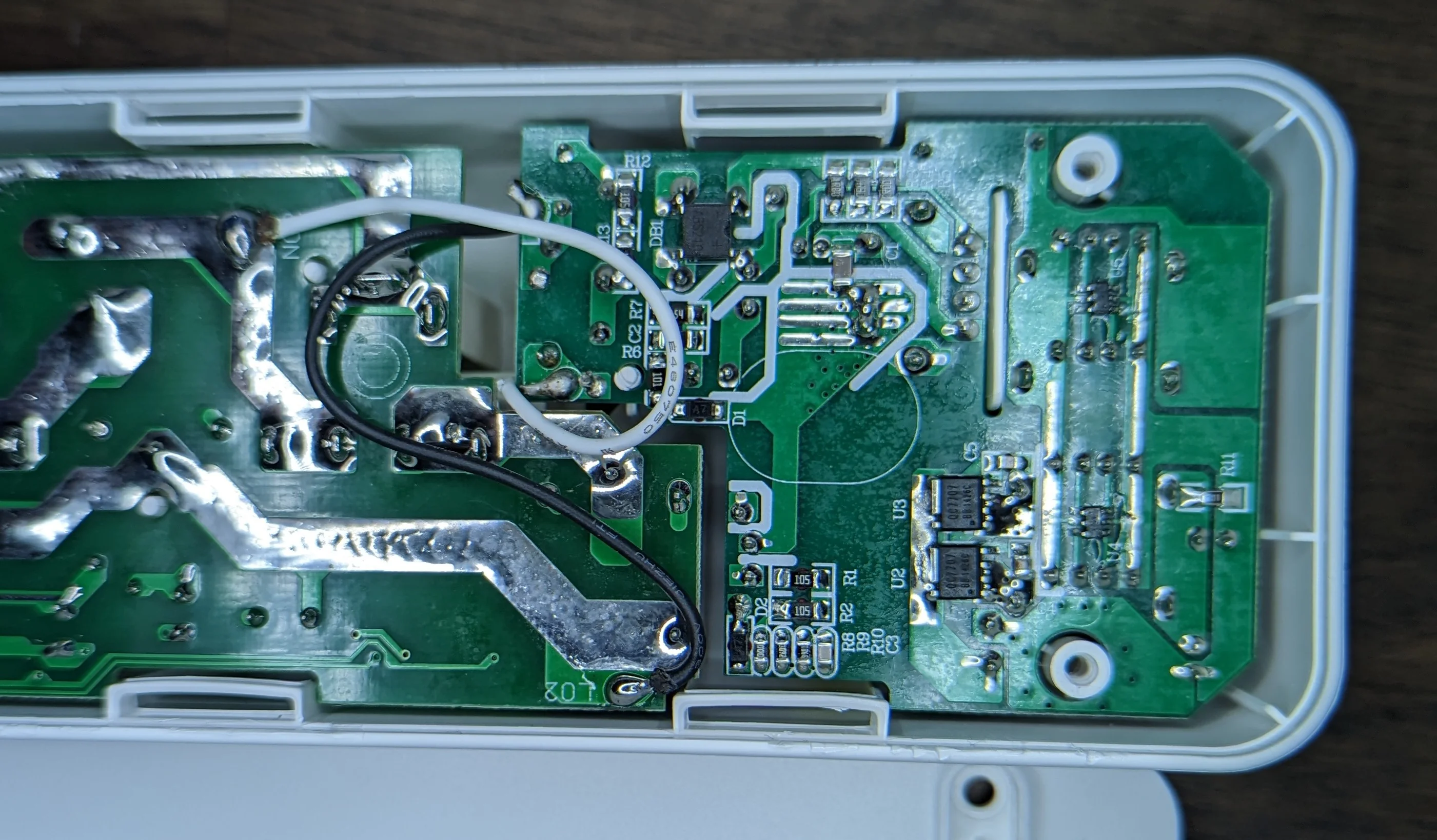
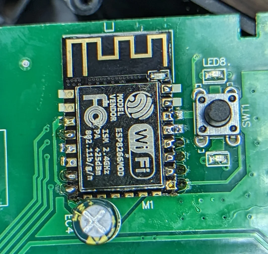
Like the USB power supply, the WiFi module is also separate from the main PCB.
You know what's cheaper than pin headers? PCB fingers in slots.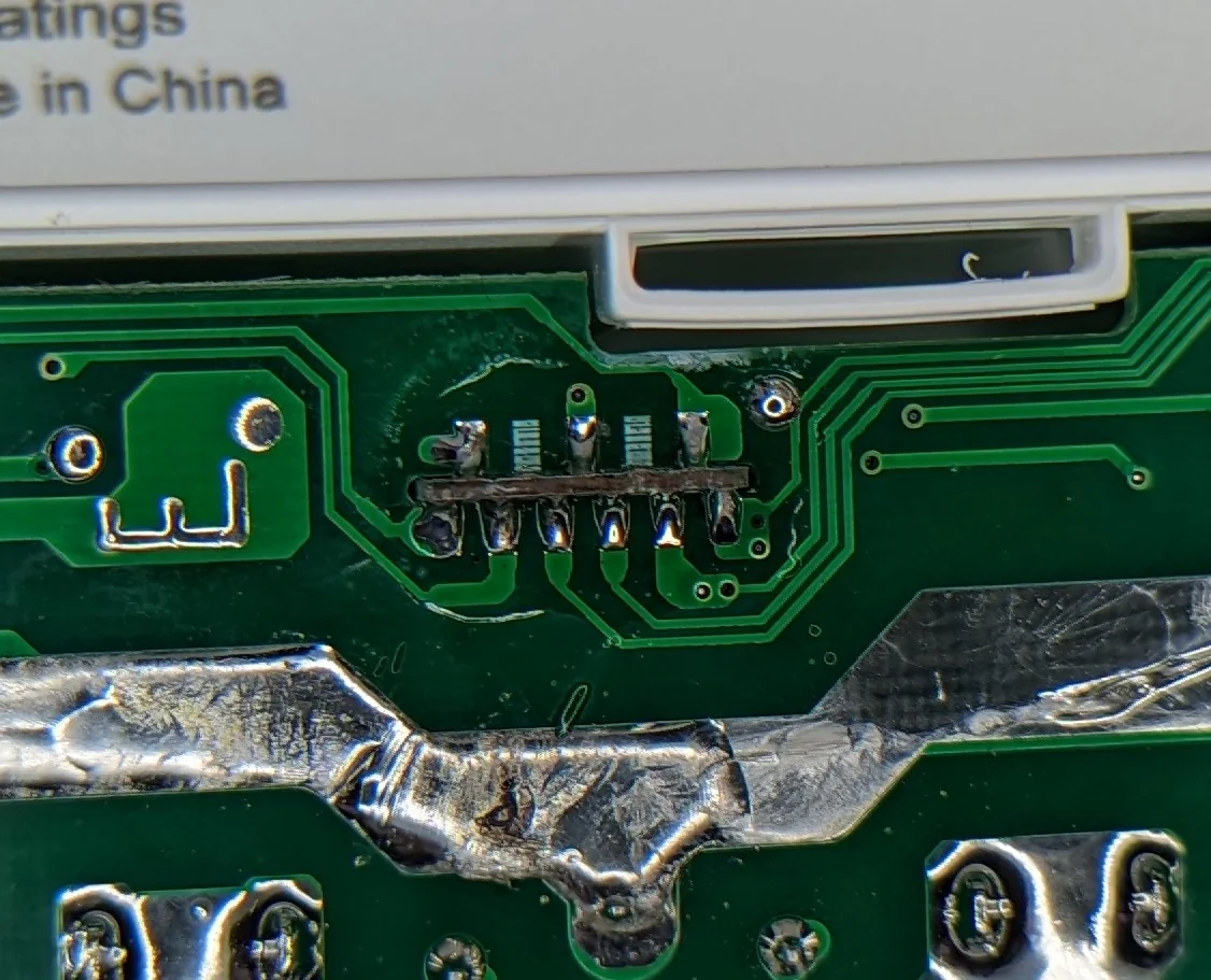
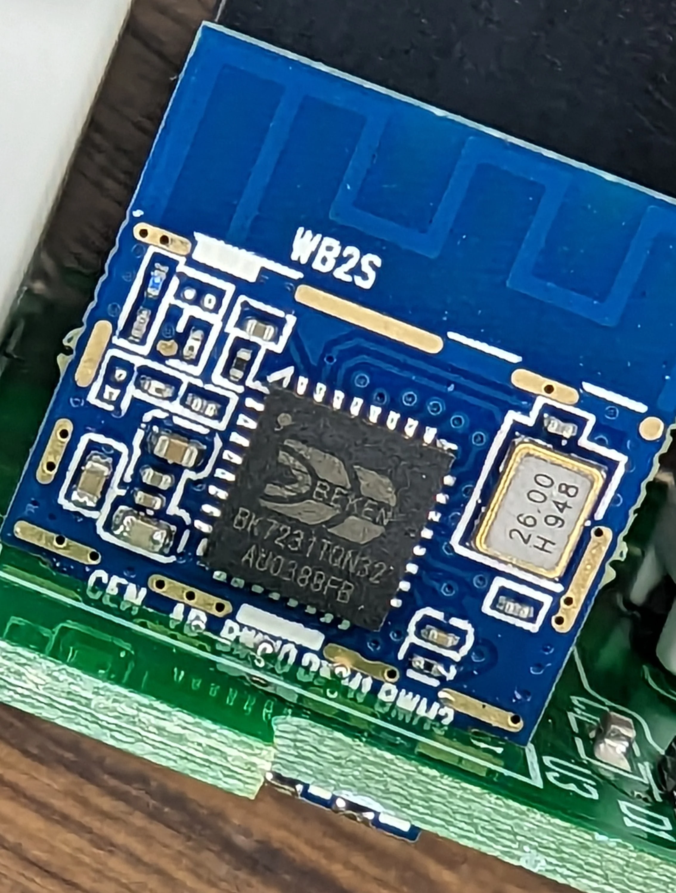
Bad news: this module is NOT an ESP powered device.
Good news: there a Tasmota-like firmware for it: OpenBK7231T!
I’ll go ahead and flash the OpenBK firmware and have a go to at least give it a try.
The relay switching electronics look reasonable enough:
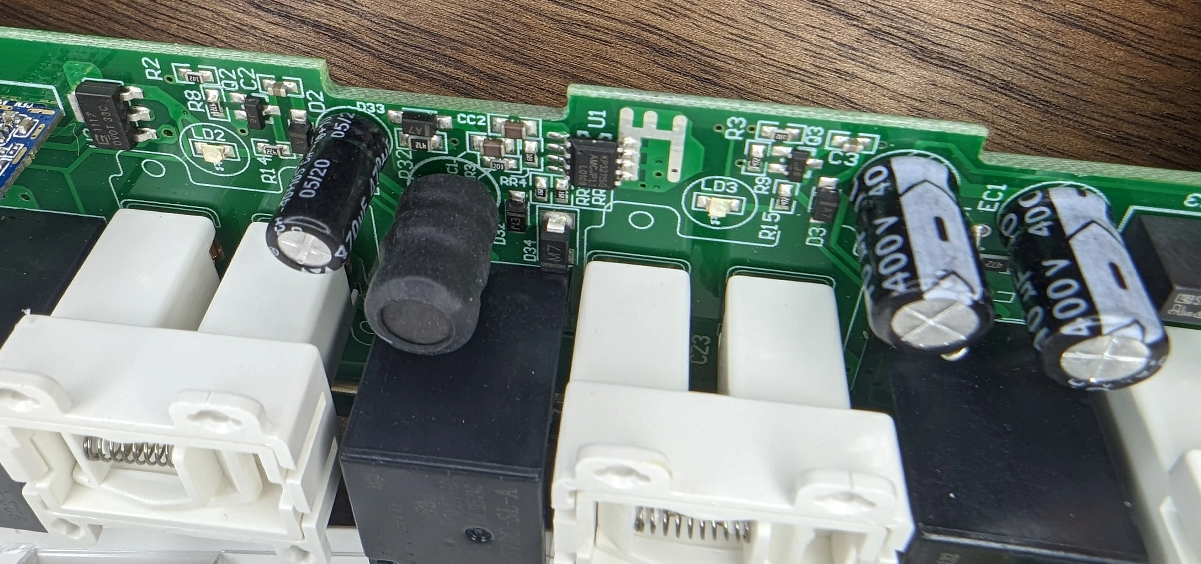
The relays themselves are nothing special to write home about:
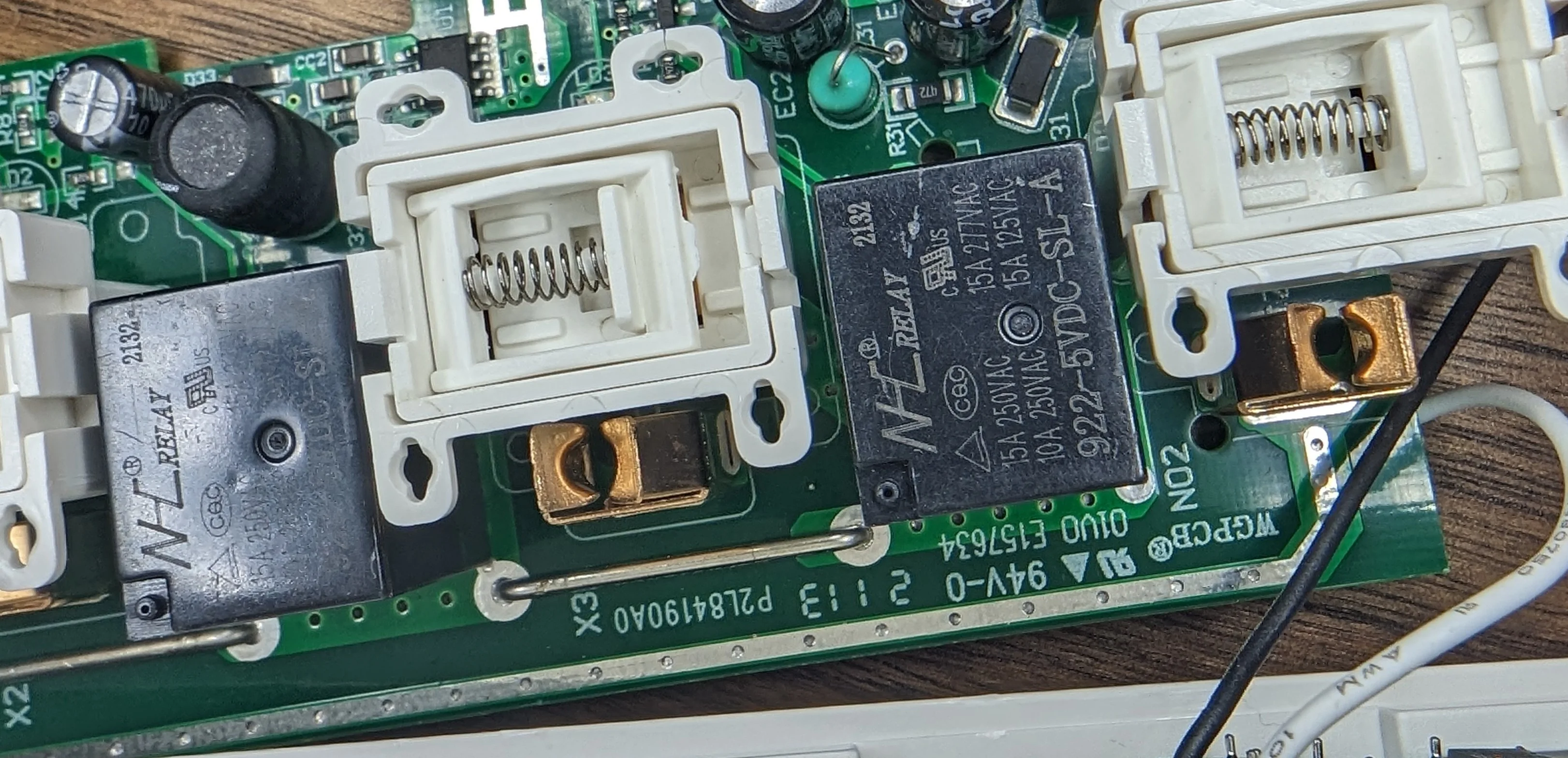
Note the links. I'd bet that it's simpler to scale a design by copy/pasting a self-contained footprint and adjust the number of links on the BOM as needed.
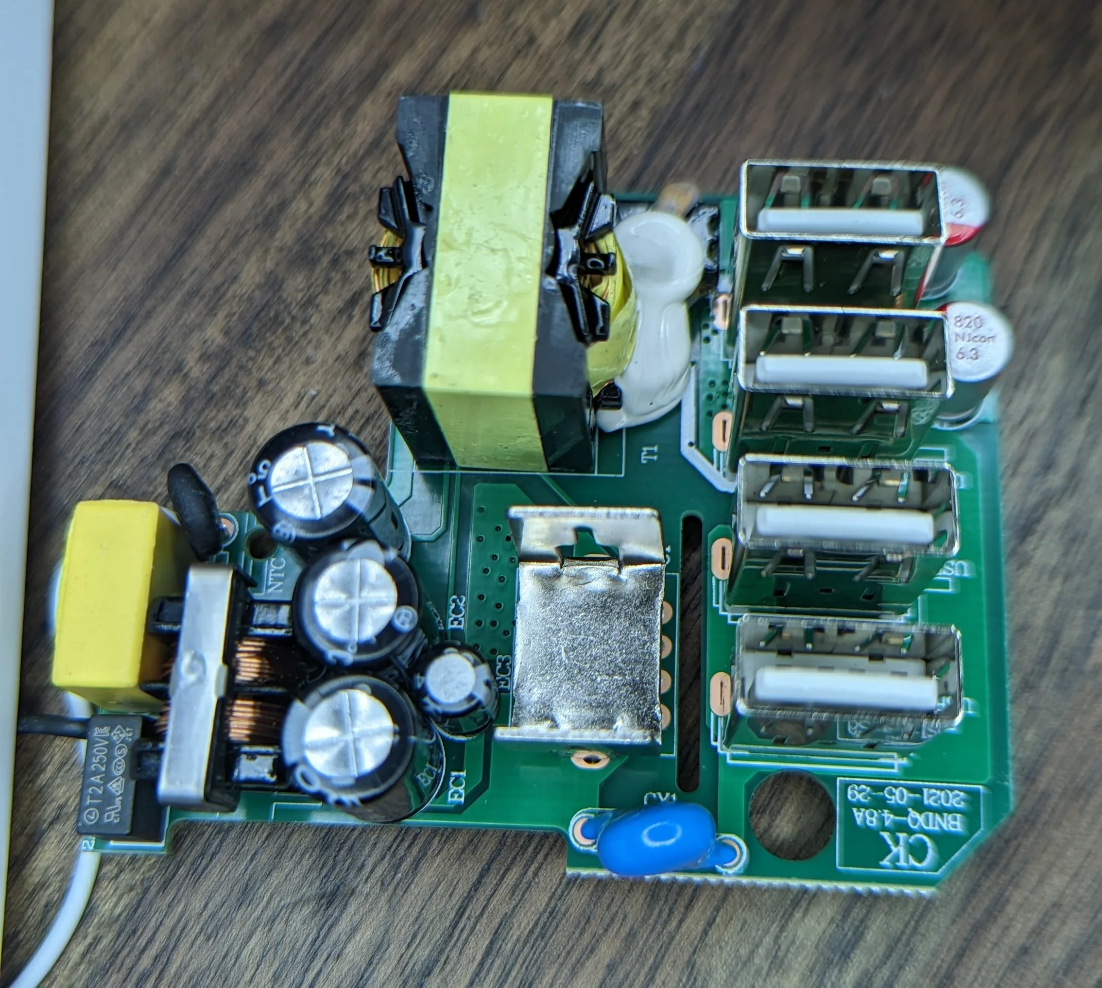
There’s nothing remarkable about the USB Power supply; standard switch mode power supply topology. The power conversion is done by the chip under the metal heat sink; I didn’t bother to get an ID on it as the ports don’t support any quick charge or power delivery protocols.
Before putting the strip back together, I secured the USB power supply wires with a bit of electrical tape to lessen the probability of a short due to insulation wearing off.
Flashing OpenBK
I don’t have a ton of notes about the flashing process as it was pretty straight forward. Two small things to note:
- The
hid_download_py/uartprogramtool needs a requirements.txt. - You can get away with only 4 wires (power, gnd, rx, tx) to program the chip but you must move very fast! It took me more than a few attempts to get the tool to connect to the bootloader on the chip; you have a very limited window for the tool to connect to the chip. I had to run connect power to the chip within about 200ms of starting the
uartprogram. If i waited much longer, I would getCannot get bus.
Eventually I was able to program the chip:
❯ python3 uartprogram ../OpenBK7231T_UA_1.15.308.bin -d /dev/ttyUSB0 -w
UartDownloader....
programm....
Cannot get bus. : |                                                  |[    ?k/s]
❯ python3 uartprogram ../OpenBK7231T_UA_1.15.308.bin -d /dev/ttyUSB0 -w
UartDownloader....
programm....
Gotten Bus...   : |                                                  |[    ?k/s]caution: ignoring unexpected reply in SetBaudRate
Write Successful: |##################################################|[ 13.2k/s]
The caution: ignoring unexpected reply came as soon as I connected the power to the programmer.
After figuring out the GPIO assignments, I did manage to get the Home Assistant / MQTT auto discovery working but - like with Tasmota - wasn’t impressed with the lack of customization in the mqtt payloads. I highly value having the correct device/entity class, icon, name … etc all populating in home assistant automatically; ESPHome lets me do this.
I’ll keep an eye on the project and may find another use for this power strip in the future.
If ESPHome ever adds support for the BK7231T chips then this is perfect.
While drafting this post, I came across an ESP based drop in replacement for the WB2S module: the WT-01N.
Had I known, I would have just done the module swap, flashed ESPHome and stopped there.
While looking for the WT-01N, on Ali Express, I found that there’s already a small supply of ESP-02S modules that should be drop in replacements!
Next time!
WT-01N swap
And here's the Tasmota configuration for the BN-Link.
BN GPIO notes
The project needs some basic “here’s how to figure out which GPIOs do what” docs similar to these but I eventually figured out the following GPIO assignments.
| PIN | Label | Purpose | Notes |
|---|---|---|---|
| 6 | PWM0 | Rel 1 | Outlet closest to the power cord. |
| 7 | PWM1 | NC | This is not connected to the main PCB. |
| 8 | PWM2 | Rel 4 | Outlet closest to the USB. |
| 10 | RXD1 | Btn | This is the user button. |
| 11 | TXD1 | WiFiLED_n | WiFi status LED. |
| 23 | ADC3 | NC | This is not connected to the main PCB. |
| 24 | PWM4 | Rel 2 | Second outlet from power cord. |
| 26 | PWM5 | Rel 3 | Third outlet from power cord. |
POWSAV
Happy that I was able to get open firmware on the first but disappointed with the lack of customization, I moved onto the second candidate.
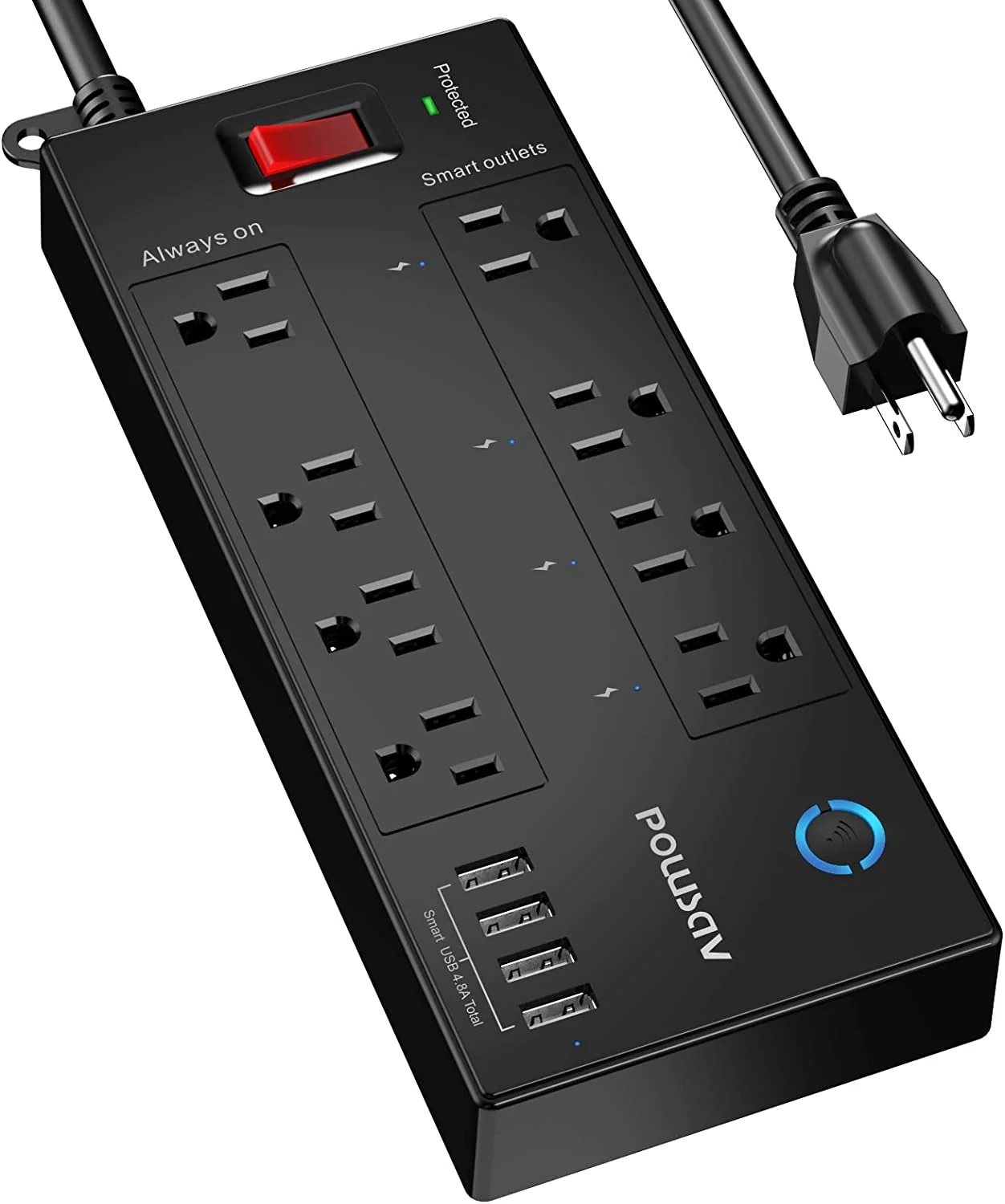
Marketing photo for the POWSAV power strip
At one point in time, this exact same device was sold under the ahrise branding and was Tasmota compatible.
The model number is the same, the templates repo picture is identical, the GPIO pinout is identical… but the linked Amazon listing is no longer available.
The PCB silk screen also include the old AHR markings so I’m guessing that this was just a re-brand with the new POWSAV branding after switching to TuYa?
To open this one, you’ll need a 2.2mm triangle bit. There are 6 screws. four hidden under the anti-slip pads.
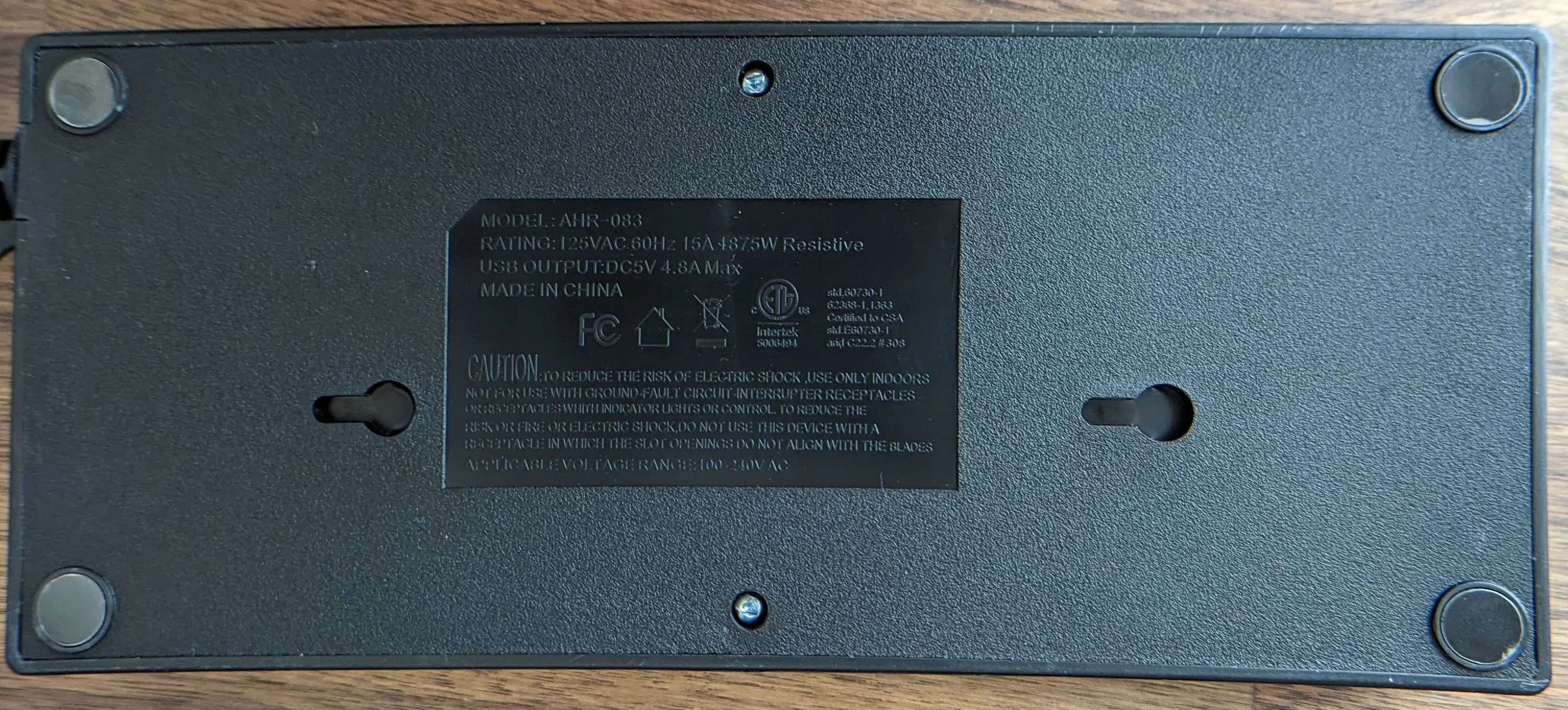
Why are the screw mounting slots not centered :/.
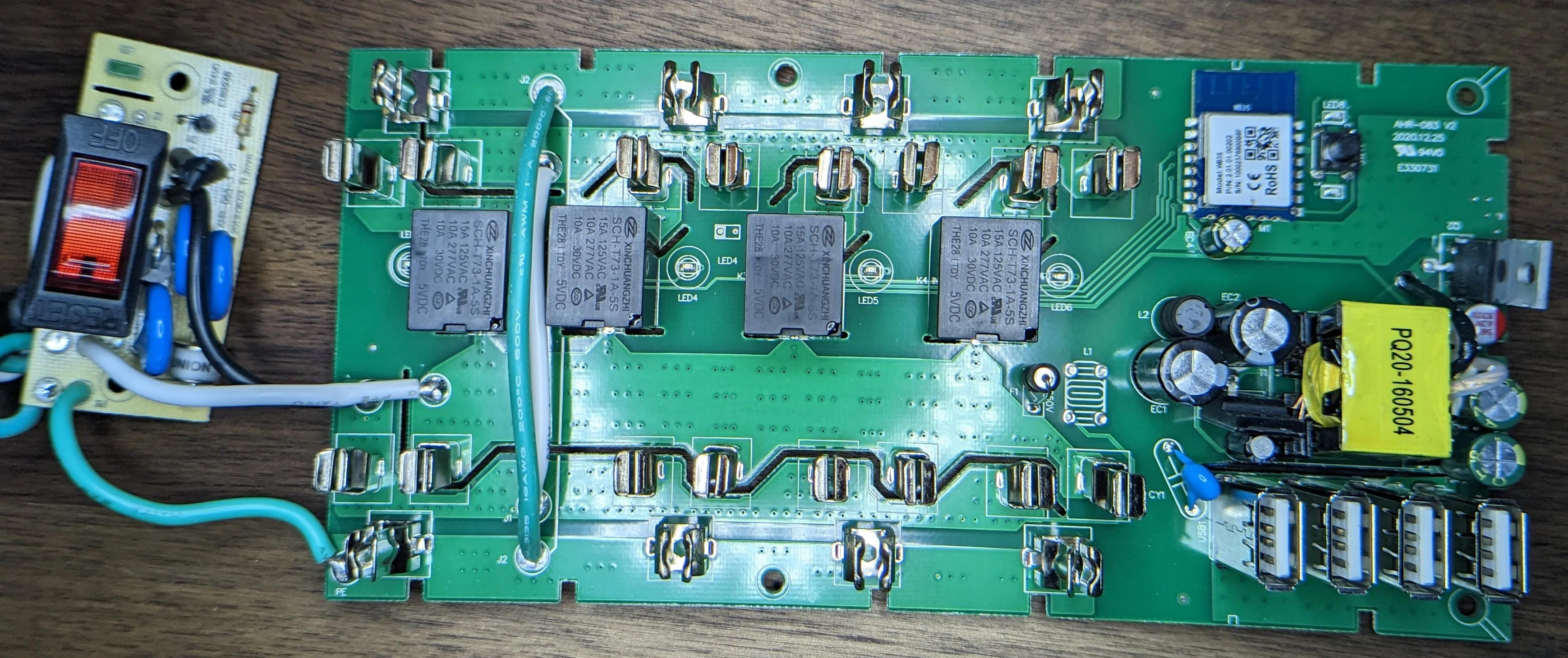
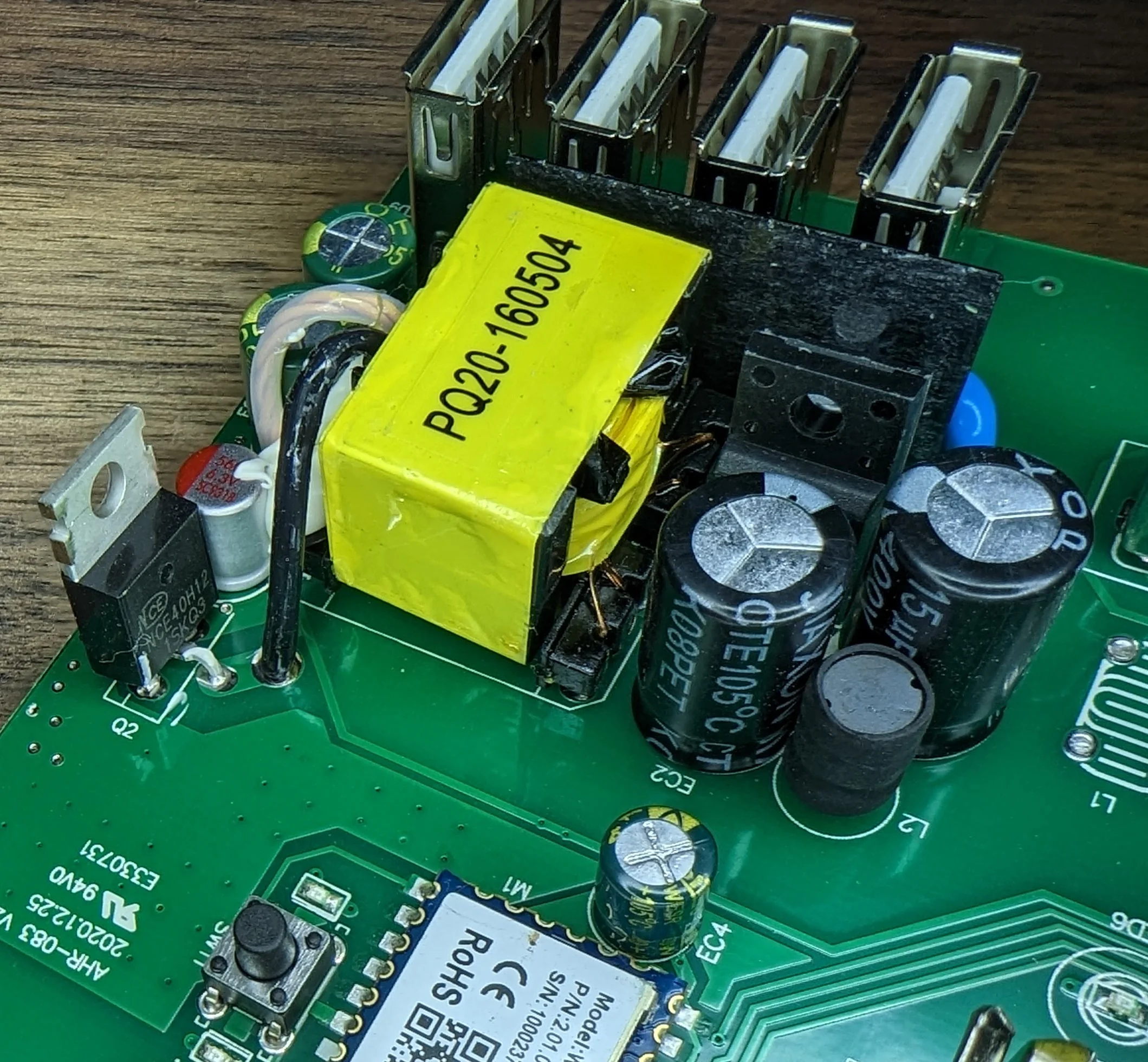
The USB, WiFI and mains switching are all on a single PCB but the main power cut off and protection features are all on a separate PCB.
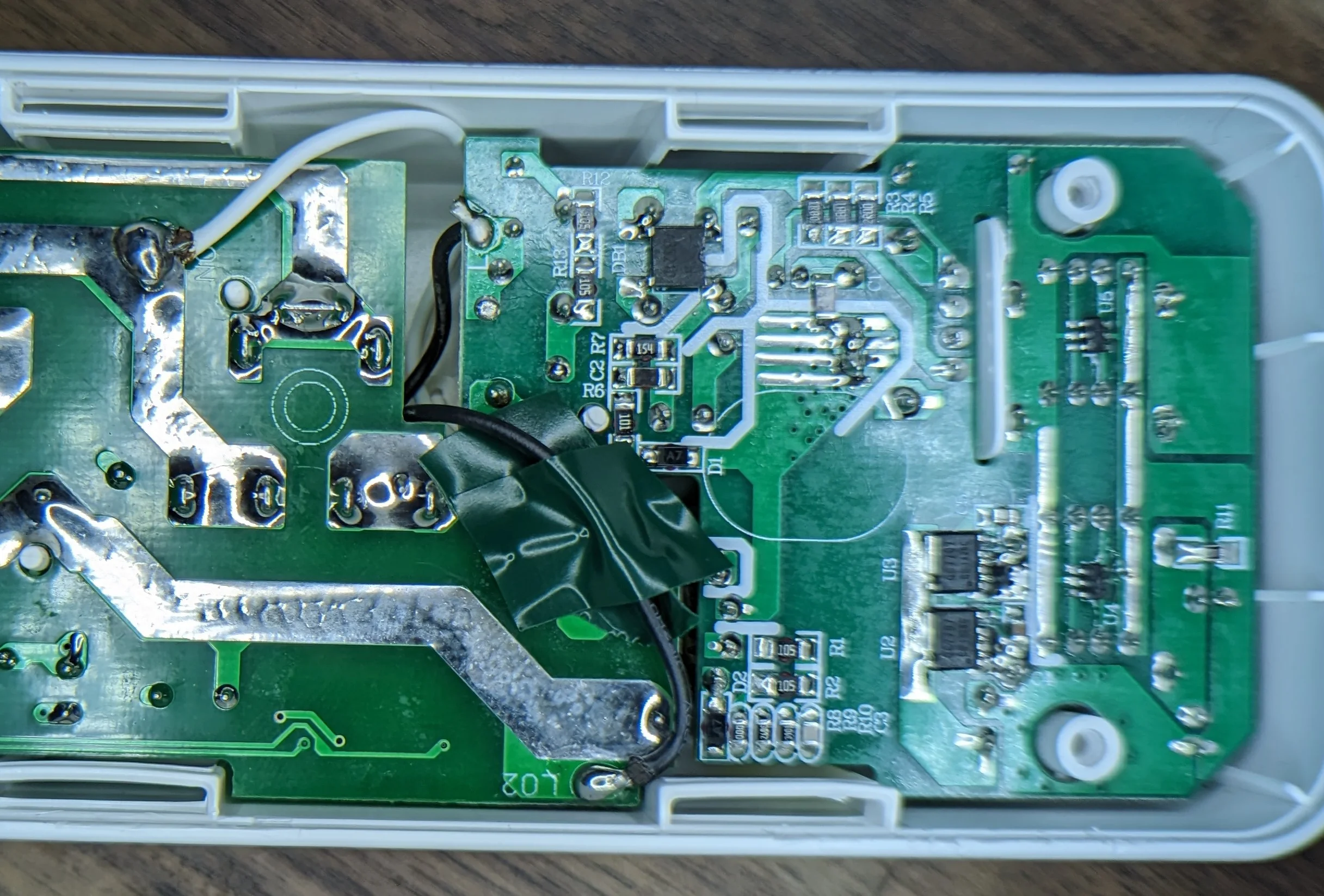
Nothing of concern to see on the bottom, everything looks pretty boring... which is good when it comes to mains handling!
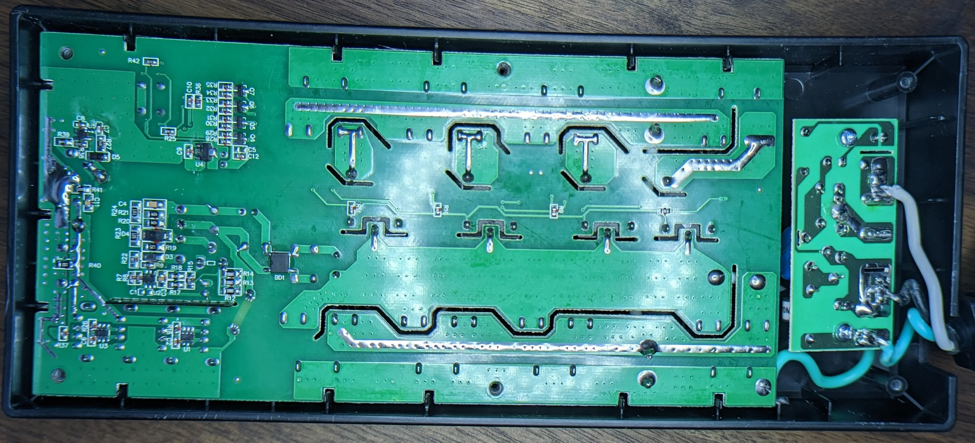
About what you'd expect for a PCB layout. Plenty of distance between the HV and LV sides!
It’s nice to see that the surge suppression circuitry is on it’s own PCB. Repairs there should be easier to pull off - in theory.
Here’s a few more shots of the primary components/assemblies:
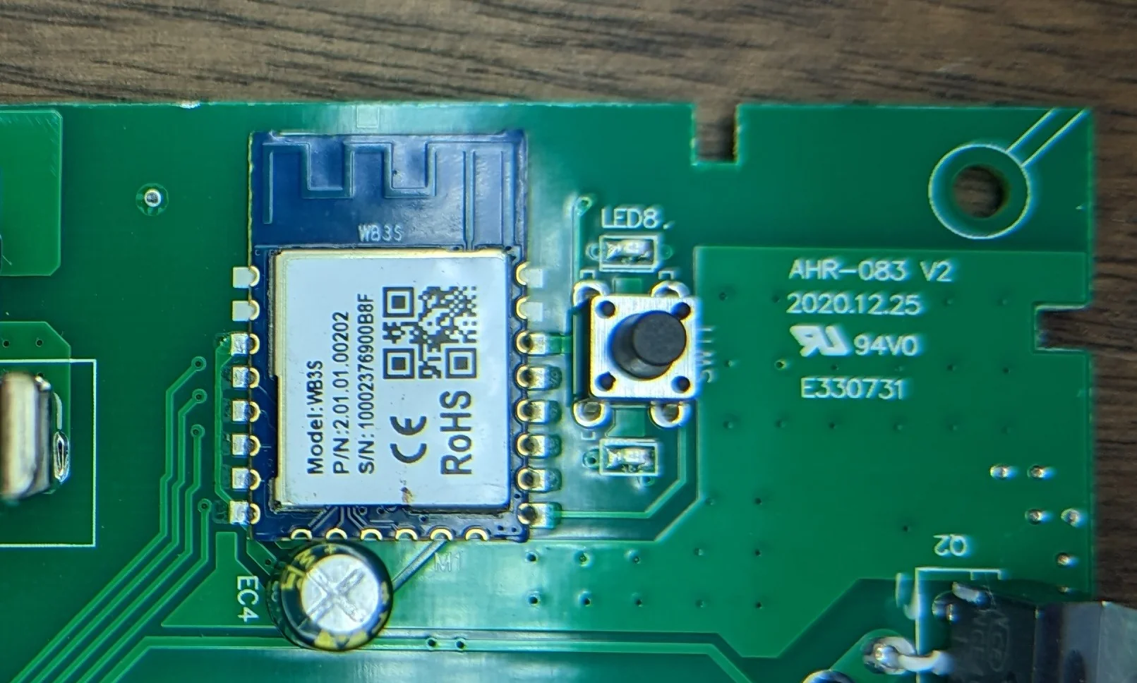
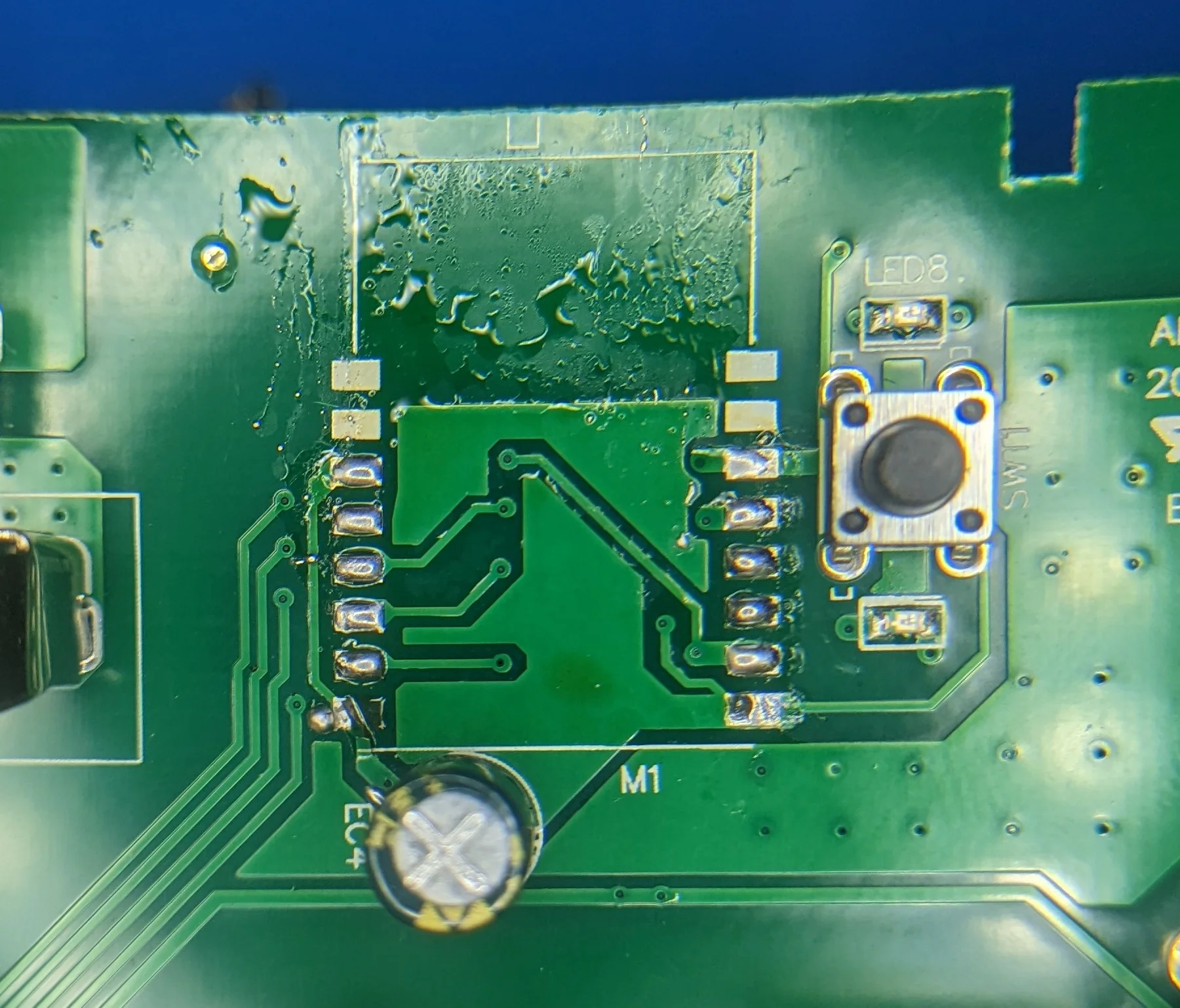
Note the silk screen: this protection PCB is common to the AHR-053 model as well. WB3S is a TuYa branded module that is pin compatible with the ubiquitous ESP-8266 modules. Note the black insulating material separating the USB ports from the mains side of things. Relatively painless extraction, only partially lifted the pad in the bottom left. Not even 5 min later, the TuYa modules has been replaced with one running a firmware powered by ESPHome.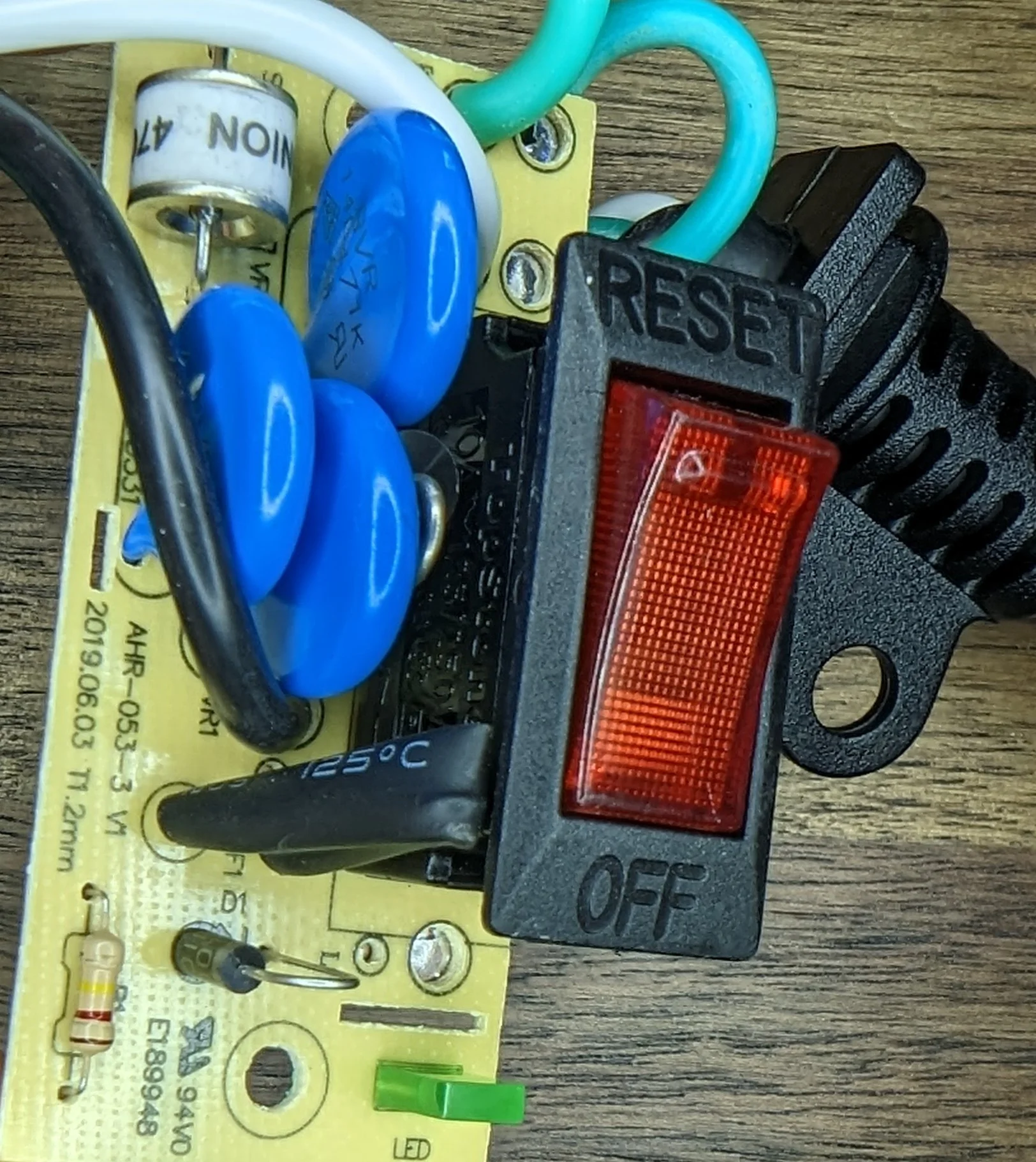
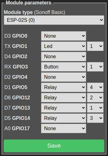
POWSAV GPIO notes
Thanks to excellent Tasmota docs, it was pretty easy to figure out the mappings.
For reference:
| PIN | Type | Number |
|---|---|---|
| GPIO2 | Led_i | 1 |
| GPIO5 | Button_n | 1 |
| GPIO 12 | Relay | 3 |
| GPIO 13 | Relay | 4 |
| GPIO 14 | Relay | 2 |
| GPIO 15 | Relay | 1 |
And the corresponding template:
{"NAME":"POWSAV_AHR-083","GPIO":[0,0,320,0,0,64,0,0,226,227,225,224,0,0],"FLAG":0,"BASE":18}Esphome
And here’s a super basic ESPHome configuration using the mappings from above.
substitutions:
  friendly_name_short: "Power Strip"

esphome:
  name: "power-strip"

esp8266:
  board: esp01_1m
  # Disable writing the switch mode / restore_from_flash
  restore_from_flash: false

status_led:
  pin:
    number: GPIO02
    inverted: True

binary_sensor:
  # I don't know what the stock behavior was. For now, only basic control
  - name: "${friendly_name_short} Button"
    platform: gpio
    internal: true
    pin:
      number: GPIO05
      mode: INPUT_PULLUP
      inverted: False

    # Press is momentary quick
    on_press:
      then:
        - switch.toggle:
            id: sw_relay1


# Not doing anything fancy so we can go with basic GPIO switches
# See: https://esphome.io/components/switch/gpio.html
switch:
  - name: "Outlet 1"
    id: sw_relay1
    platform: gpio
    pin: GPIO15
    icon: "mdi:numeric-1"
    # Don't want to wear down flash storing state, easiest to just not bother remembering
    restore_mode: ALWAYS_OFF
    # See: https://developers.home-assistant.io/docs/core/entity/switch/#available-device-classes
    device_class: OUTLET

  - name: "Outlet 2"
    id: sw_relay2
    platform: gpio
    pin: GPIO14
    icon: "mdi:numeric-2"
    restore_mode: ALWAYS_OFF
    device_class: OUTLET

  - name: "Outlet 3"
    id: sw_relay3
    platform: gpio
    pin: GPIO12
    icon: "mdi:numeric-3"
    restore_mode: ALWAYS_OFF
    device_class: OUTLET

  - name: "Outlet 4"
    id: sw_relay4
    platform: gpio
    pin: GPIO13
    icon: "mdi:numeric-4"
    restore_mode: ALWAYS_OFF
    device_class: OUTLET