Integrating ESPHome with a cheap Geiger Counter
Yes, there have been loads of people doing similar things! ESPHome already has a tutorial covering exactly this!
I’m writing this up because the approach that I ended up taking was not the intended/planned approach.
The Geiger Counter
I originally pulled the trigger on this particular version because it had a built in screen attached to a micro controller.
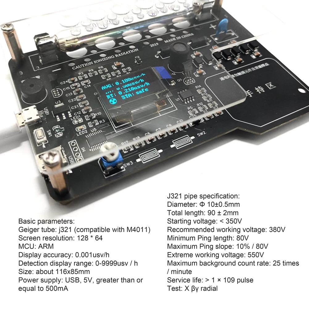
I naïvely thought that I’d be able to get a simple UART from the 4 pins next to the microcontroller or maybe even get data directly off of the micro USB port.
DIY Geiger Counter Kit Assembled Module Nuclear Radiation Detector X γ β rays Iodine 131 Detecting OLED Display Radiation TesterThe USB / UART port
After receiving and unpacking it, I probed around and determined that the micro USB port did have the data lines going to the U5 micro and that the 4 pins also went to the micro.
Unfortunately both seemed dead; the pins didn’t have any signal on them and the software on the micro implementing the USB stack didn’t seem to be fully implemented.
Using dmesg I could see a device being plugged in but the device failed to respond to any probes.
So much for the easy way out.
Plan B
With the identifying markings sanded off of the chip, attempting to dump / reverse / re-program the firmware wasn’t the most appealing option.
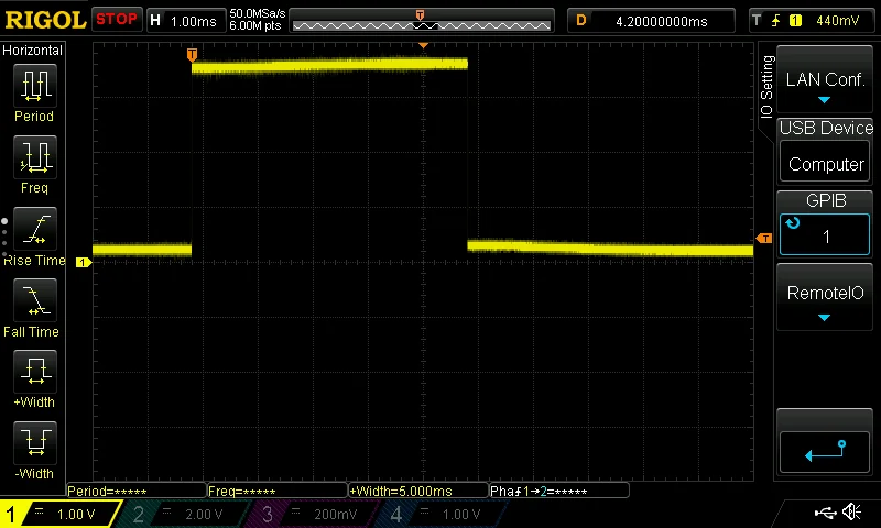
After some quick testing, I determined that the micro controller toggles the beeper and the LED via distinct GPIO pins and that the LED is pulsed to 3.3v for 5ms.
For reference, here are the points that I chose to inject power and observe the LED. I am injecting 5V into the geiger counter from the ESP module so I can program and power the entire assembly with a single cable. If you choose to use separate power supplies for both, make sure that the ESP and geiger counter share a ground!
Removing R1 is optional; keep it if you want the beeper to click as well.
I have some thoughts on being able to toggle this behavior below

I left R1 in place so it's easier to reverse the mod.
And with a bit of hot glue, we’re done with the hardware assembly.
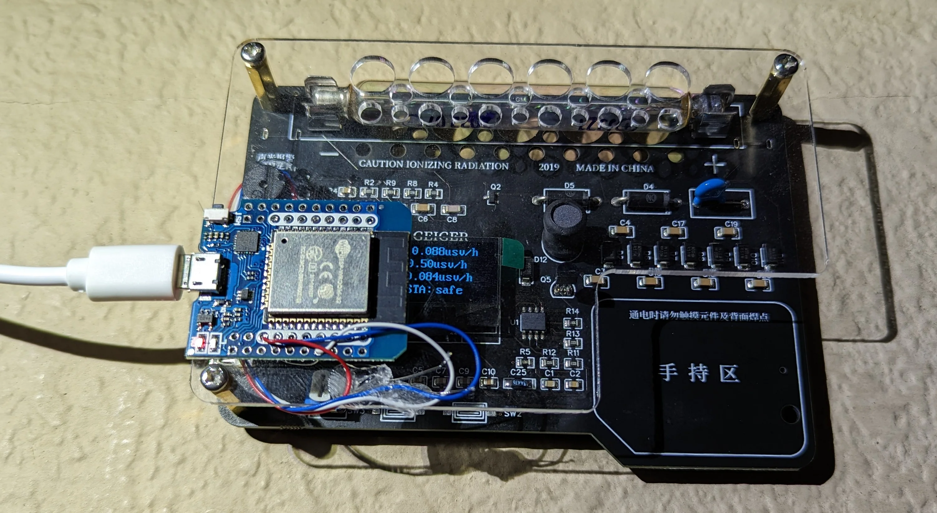
There's no good place for the ESP module so I chose to strategically obfuscate the portion of the screen that does not display the actual measurements.

I wouldn't put the ESP right here because a) the tube is partially obstructed and b) the tube is charged to a few hundred volts and putting any delicate electronics that close seems like a bad idea.
ESPHome
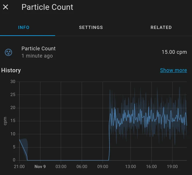
Ignore that 12 hour gap in the data... I forgot to plug the assembly back in after doing some tests.
The firmware is pretty simple. The configuration below is an abridged version of what I am currently using. I’ve stripped out unnecessary things but left some comments in to serve as basic documentation.
##
# To convert from particles per unit time, there's supposed to be some conversion factor.
# This conversion factor depends on the tube and the cheap Ali Express tubes all seem to be J321 style.
# Not a ton of documentation out there, but I did find one source that says J321 is basically J305.
# See: https://www.radmon.org/index.php/forum/geiger-muller-tubes/1245-information-on-j321-gm-tube
#
# But even then, the conversion factor is derived from some known isotope. They expose the tube to some
#   known isotope and then measure the counts. Because they also know the proper dosing info for the
#   isotope, the tube then gets a conversion factor.
#
# Additionally, the micro controller sits between the raw data from the tube and the LED that I am tapping into.
# Each time there is _any_ radiation detected, the micro controller pluses the LED for 5ms. In theory, multiple
#   radioactive particles could strike the tube in the 5ms window and the microcontroller would know ... but I wouldn't.
# At 5ms per pulse, the maximum number of particles per second that I can detect is 200. Even if the TRUE count
#   is 3x that... 200 is still way more than enough to know that _something_ isn't right and that's really what I'm after here.
#
# So for now, just stick with basic counts per min w/ the understanding that the signal that I'm observing might not
#   be with the full resolution that the tube is capable of.
##
esphome:
  # Note: this will be the hostname that device request during the DHCP dance...
  name: "geiger-counter"

esp32:
  board: mhetesp32minikit

# Enable logging
logger:
  level: INFO

sensor:
  # See: https://esphome.io/components/sensor/pulse_counter.html
  - name: Particle Count
    platform: pulse_counter
    id: sense_p_cnt
    # Does not really matter which pin for ESP32
    pin: GPIO32
    use_pcnt: true
    # Measured with oScope: pulse is 5ms _exactly_.
    # Docs say to use falling edge detection with the hardware pulse counter
    count_mode:
        rising_edge: DISABLE
        falling_edge: INCREMENT
    # Docs ALSO say that you can't configure a filter of more than 13us when using the
    #   internal pulse counter. 5ms is ... 5000 us and that's more than 13us so I guess we'll
    #   stick with the defaults?
    ##
    internal_filter: 13us

    # As best I can tell, pulses trigger an ISR which just increases some counter somewhere.
    # Every update_interval, esphome checks the value in the storage and computes the count
    #   per min.
    ##
    update_interval: 60s
    unit_of_measurement: "cpm"
    state_class: "measurement"
    icon: "mdi:radioactive-circle-outline"
Beeper
I can’t confirm it, but I suspect that the beeper is driven independently of the LED because the original designer wanted to implement a software toggle for the sound.
I don’t need the sound functionality but I also don’t want to permanently disable it. It would be nice to be able to toggle it on/off as needed. There are a few ways to get similar functionality:
Hack the hardware… more. The TO92 driving the beeper (via
R1) is aSS9014 NPN. I could add another transistor in series withR1and then control the current flow via another GPIO on the ESP.Inspired by this reddit thread, I could try to get the ESP to toggle a beeper directly when a pulse is detected. There are some issues with this approach, though.
It is not possible to get direct access to the ISR via ESPHome. I’d have to create my own custom component to pull this off. Not the end of the world but also more time than I wanted to spend so I went with a different approach that appears to work.
Basically, create two instances of the pulse_counter sensor using the same GPIO pin.
One of them will remain external and will publish data to Home Assistant at 60s intervals.
The other will be internal and will be updated every loop().
By attaching a lambda function to the sensor evaluation loop, we can compare the number of recorded pulses many times per second.
The number of cycles that the internal pulse counter will sum pulses over is 1 so any time the current value does not match the previous value … should indicate that a pulse was fired off.
Here’s what I came up with:
sensor:
  # See: https://esphome.io/components/sensor/pulse_counter.html
  - name: Particle Count
    # <...>
  - name: INTERNAL Particle Count
    internal: true
    platform: pulse_counter

    # <... literally the exact same config as the external pulse counter ...>
    ##
    # 0ms means every loop()
    update_interval: 0ms

    filters:
      # LogE because we want it to stand out on the console while testing
      - lambda: |-
          static int num_zeros = 0;
          if (x > 0) {
            // reset
            num_zeros = 0;
            // Indicate that a non 0 measurement was taken and dump to console
            // This is where a beeper would be fired off if desired...
            ESP_LOGE("filterLambda", "raw is %f", x );
          } else {
            num_zeros++;
          }
          // Dont spam console
          if (num_zeros % 1000 == 0) {
            ESP_LOGI("filterLambda", "num_zeros is %d", num_zeros );
          }
          return x;
In testing, I would get logs like:
[17:34:18][E][filterLambda:165]: raw is 10000.000000
[17:34:18][I][filterLambda:170]: num_zeros is 0
[17:34:19][E][filterLambda:165]: raw is 10000.000000
[17:34:19][I][filterLambda:170]: num_zeros is 0
[17:34:19][E][filterLambda:165]: raw is 10000.000000
[17:34:19][I][filterLambda:170]: num_zeros is 0
[17:34:20][E][filterLambda:165]: raw is 10000.000000
[17:34:20][I][filterLambda:170]: num_zeros is 0
[17:34:22][E][filterLambda:165]: raw is 10000.000000
[17:34:22][I][filterLambda:170]: num_zeros is 0
[17:34:24][E][filterLambda:165]: raw is 10000.000000
[17:34:24][I][filterLambda:170]: num_zeros is 0
[17:34:24][E][filterLambda:165]: raw is 10000.000000
[17:34:24][I][filterLambda:170]: num_zeros is 0
[17:34:25][E][filterLambda:165]: raw is 10000.000000
[17:34:25][I][filterLambda:170]: num_zeros is 0
[17:34:26][E][filterLambda:165]: raw is 10000.000000
[17:34:26][I][filterLambda:170]: num_zeros is 0
[17:34:32][E][filterLambda:165]: raw is 10000.000000
[17:34:32][I][filterLambda:170]: num_zeros is 0
[17:34:33][E][filterLambda:165]: raw is 10000.000000
[17:34:33][I][filterLambda:170]: num_zeros is 0
[17:34:35][E][filterLambda:165]: raw is 10000.000000
[17:34:35][I][filterLambda:170]: num_zeros is 0
[17:34:40][E][filterLambda:165]: raw is 10000.000000
[17:34:40][I][filterLambda:170]: num_zeros is 0
[17:34:42][E][filterLambda:165]: raw is 10000.000000
[17:34:42][I][filterLambda:170]: num_zeros is 0
[17:34:43][E][filterLambda:165]: raw is 10000.000000
[17:34:43][I][filterLambda:170]: num_zeros is 0
[17:34:44][E][filterLambda:165]: raw is 10000.000000
[17:34:44][I][filterLambda:170]: num_zeros is 0
[17:34:45][E][filterLambda:165]: raw is 10000.000000
[17:34:45][I][filterLambda:170]: num_zeros is 0
[17:34:46][E][filterLambda:165]: raw is 10000.000000
[17:34:46][I][filterLambda:170]: num_zeros is 0
[17:34:47][E][filterLambda:165]: raw is 10000.000000
[17:34:47][I][filterLambda:170]: num_zeros is 0
[17:34:50][E][filterLambda:165]: raw is 10000.000000
[17:34:50][I][filterLambda:170]: num_zeros is 0
[17:34:52][E][filterLambda:165]: raw is 10000.000000
[17:34:52][I][filterLambda:170]: num_zeros is 0
[17:34:54][E][filterLambda:165]: raw is 10000.000000
[17:34:54][I][filterLambda:170]: num_zeros is 0
[17:34:58][E][filterLambda:165]: raw is 10000.000000
[17:34:58][I][filterLambda:170]: num_zeros is 0
[17:35:00][E][filterLambda:165]: raw is 10000.000000
[17:35:00][I][filterLambda:170]: num_zeros is 0
[17:35:02][E][filterLambda:165]: raw is 10000.000000
[17:35:02][I][filterLambda:170]: num_zeros is 0
[17:35:05][E][filterLambda:165]: raw is 10000.000000
[17:35:05][I][filterLambda:170]: num_zeros is 0
[17:35:11][I][filterLambda:170]: num_zeros is 1000
[17:35:17][E][filterLambda:165]: raw is 10000.000000
[17:35:17][I][filterLambda:170]: num_zeros is 0
The period between 17:34:18 and 17:35:17 is basically 60 seconds long and the number of times that num_zeros is 0 is printed is 27.
Coincidentally, the external facing sensor published a value of 27 to Home Assistant.
This is not a conclusive test but - at least at background radiation levels - using two instances of the same sensor type on the same GPIO might work.
I don’t have any easy way to induce higher counts on the geiger tube so I can’t test how well this holds up “under load” nor can I confirm that this works reliably across all ESP chips/modules and versions of ESPHome/PlatformIO…etc.
Doing this with a custom component probably is the better way to do it but I wasn’t going to pull that off in the time I had allotted.