Enhanced Home Assistant Switch Plate (HASP)
The HASwitchPlate project by aderusha is brilliant. He’s managed to arrange some relatively cheap commodity hardware into a package that conveniently fits into a prime location for interacting with Home Automation - the light switch. The entire package sips power off of the already present mains wiring and connects to any MQTT broker via the esp8266 chip. As the HASP was designed to be used with Home Assistant, the humble 2.4 inch LCD transforms into an accessible control surface for an incredibly powerful home automation platform!
Modifications
First, a brief word about indemnification:
All instructions and information on this page is purely for informational purposes.
The original HASP and my modifications come with neither an expressed or implied warranty. By constructing your own, you assume all risk.
Software
The few software modifications I’ve made to the HASP project are relatively small and don’t implement anything significant or new; they are ‘quality of life’ improvements that target small portions of the code.
I strongly believe that the hardest part of using a given piece automation technology should be taking it out of the box. To wit, Home Assistant has robust - but not perfect - support for automatic device discovery and configuration via MQTT. Once a device has connected to the MQTT broker, it simply publishes a document detailing how HA should interface with the device. It’s a wonderful experience to see a new device connect to the network for the first time and just a few seconds later the new device is registered in HA, waiting for you to start integrating it into automations 🤩🤤.
While there are quite a few sensors/stateful-attributes in the original HASP code, none of them automatically present themselves to Home Assistant 😔. I set about fixing that to the best of my abilities. Unfortunately, the LCD backlight is the only peripheral that could be ‘upgraded’ to automatic configuration without making a ton of changes to the original code base.
All of the hardware modifications detailed below automatically configure themselves with Home Assistant.
The original HASP code base uses allocates too little memory for storing MQTT credentials. Any username or password longer than 31 bytes/characters would be silently truncated on save. Despite the ‘credentials saved, rebooting’ message, the next screen was always a ‘failure to connect’ message. Frustrating! The pull request to address this is here.
Hardware
The HASP does support dimming the LCD, but it has no awareness of ambient light levels. This makes it rather difficult to deploy a HASP in any ’light sensitive’ location like a bedroom or media room without another device to cue Home Assistant and lower the LCD brightness. Workable, but too high friction to be ideal.
Light Dependent Resistors - LDR for short - are a very cheap and compact way to get an approximate light level. Fortunately, the analogue pin is broken out on the PCB so a simple resistive divider and a few lines of code are all that’s needed to get a a number that linearly correlates to the level of light hitting the face plate.
It just so happens that there is just enough room to fit a LDR beneath the surface of the decor plate and out of the way of the LCD. As (not) shown in the picture above, there is no way to tell that the LDR is embedded beneath the surface.
The range of values from the LDR isn’t great, but they are adequate enough to reliably detect if the HASP is in a darkened room.
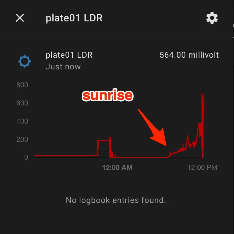
ignore the spikes just before noon, those are due to to testing with a flash light
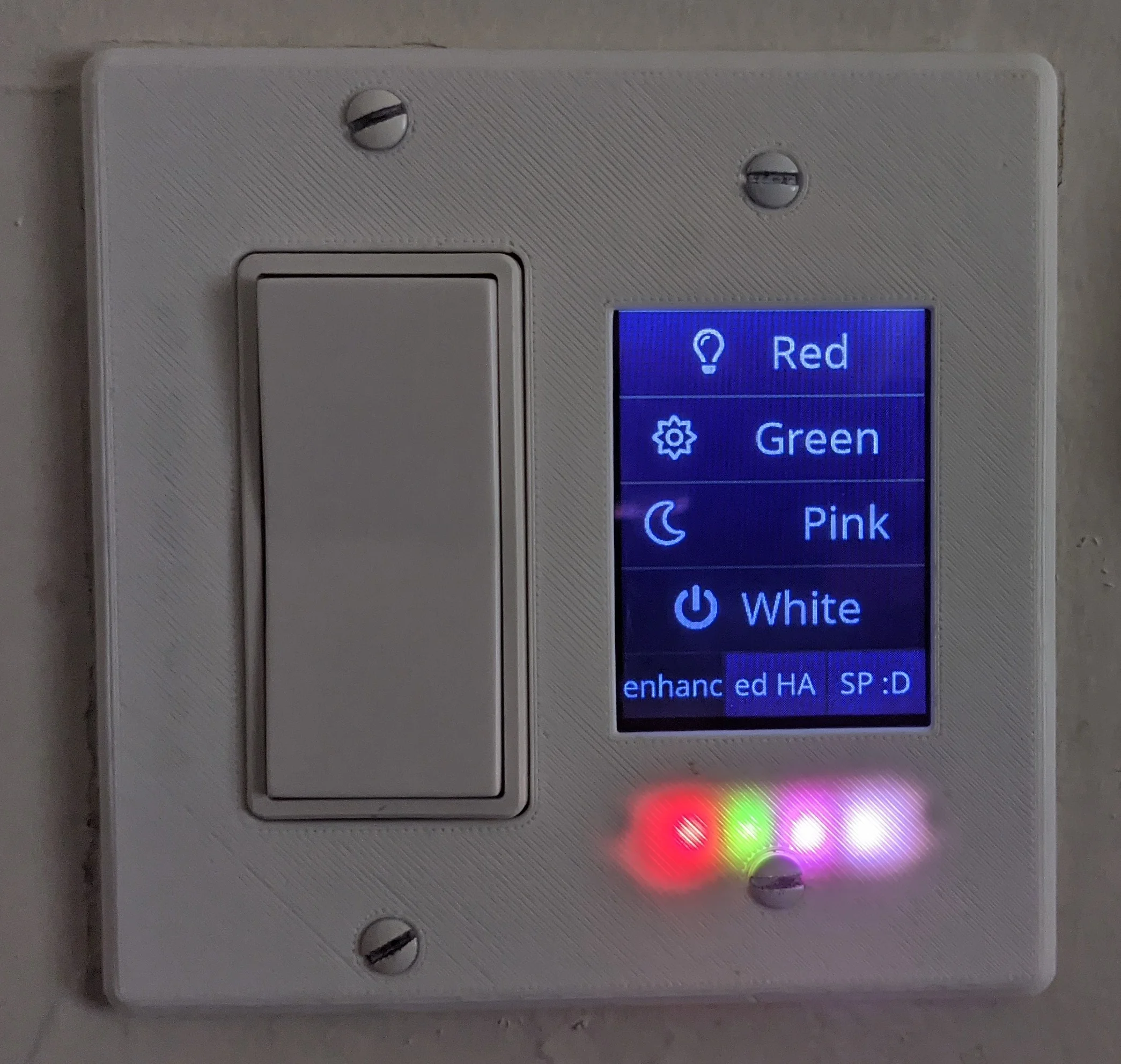
While researching potential ways to measure the ambient brightness, I stumbled across the HomeSeer HS-WD200+ which features a rather novel way to convey additional information to a user; seven RGB leds 😍. It’s a brilliant use of such a simple and ubiquitous technology that I’m not really sure why every smart switch doesn’t do this!

HomeSeer's WS200 has a delightful innovation... RGB LEDs!
With zero room to spare, four LEDs can fit into a small cavity between the LCD and decor plate surface. Like with the LDR, there is no visual ’tell’ that there are LEDs beneath the surface… unless they’re on, of course.
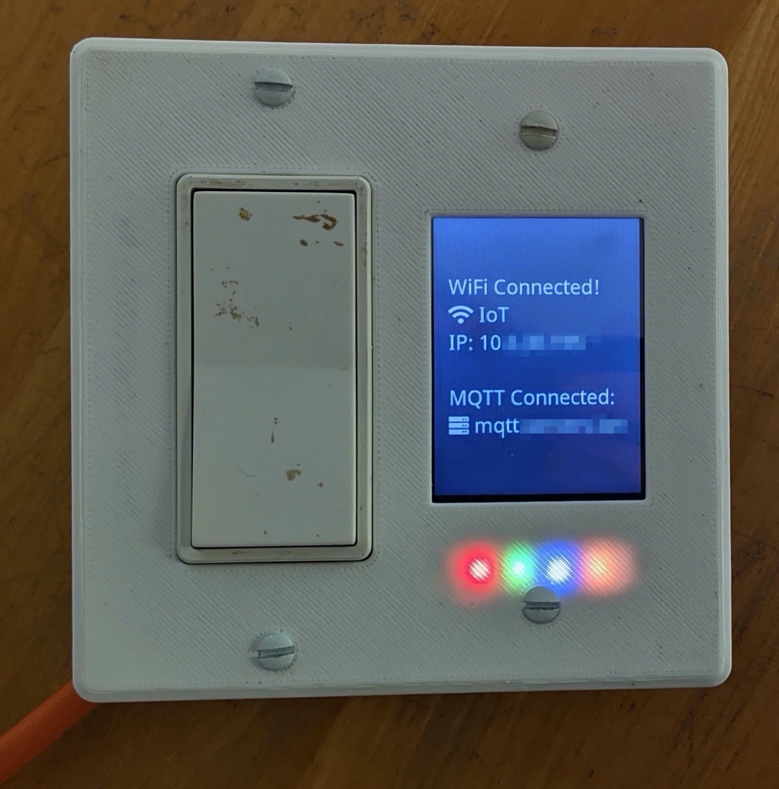
Ignore the dirt on the switch. Notice how you can't tell there's an LDR beneath the surface
The enclosure
Without consuming more than 1 gang, the only realistic way to get the wires for the new components to the HASP PCB is to go around the edge of the LCD’s PCB. This is accomplished with two small ‘channels’ that slightly protrude in the vertical directions from the lip around the LCD and into the box that encloses the electronics.
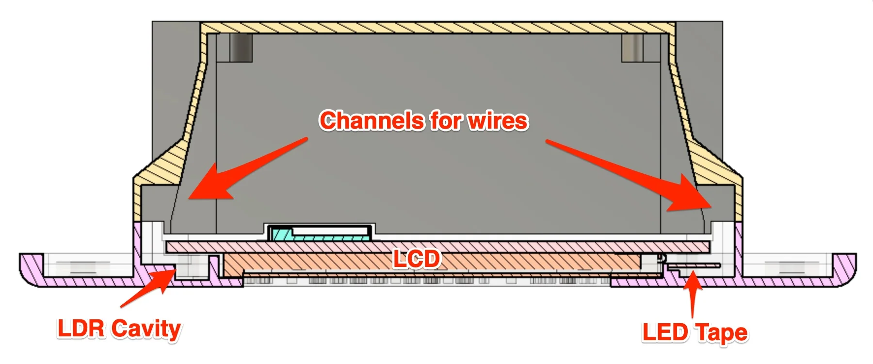
Section analysis from f360 showing small channels around the LCD for wires to LDR and LEDs
Additionally, I found that the original printed parts do not properly fit in the two gang electrical box where I intended to deploy the HASP.
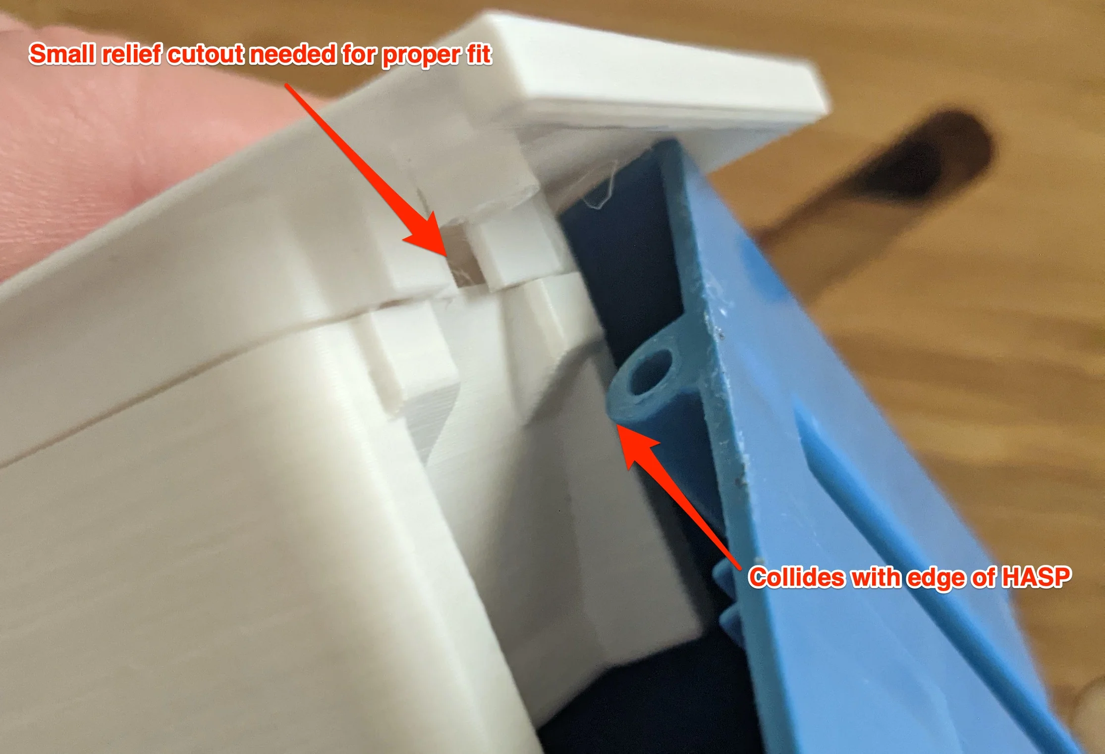
The only way to fit the HASP in my 2-gang electric boxes is to cut out a small section
In total, the modifications required to accommodate the LDR and LED tape are relatively small, but I had to re-create the model from scratch so several things are likely a bit different from the original model. It should be relatively easy to port the modifications to the other multi-gang configurations that the original HASP supports.
The .step and .f3z files are available should you want to make the necessary modifications to other switch plate configurations.
The .stl and .3mf files are available for easy printing.
All files available below and on github.
Assembly
The steps below are meant to be followed between the original steps 03_Electronics_Assembly and 04_Project_Enclosure.
In short, you’ll want to assemble and test the HASP PCB as in the original instructions, but use the steps below as a substitute for the enclosure assembly process.
Additional Materials
In addition to everything in the original BOM, you’ll need:
A LDR. Be aware that LDRs come in many different shapes and sizes and have different resistance values. Space is rather tight, so the form factor matters a lot more than the resistance values or band of light that the LDR responds to. If you use a different LDR, you may need to adjust the resistor value to better match your LDR. You can get 50 of the exact model GL5516 that I used for less than $2 here.
A 10KΩ resistor to form a simple resistive divider with the LDR. This will better map the the full range of the LDR to the 0-1 volt range that the ESP8266 ADC uses. Space is rather limited so the smaller the resistor, the better; no need for anything larger than 1/4 Watt. You can get a 10-pack of 10KΩ resistors here
WS2812B LED tape featuring the 3535SMD package. The ‘regular size’ LED package will not fit so make sure you use the smaller
3535SMDpackage! Beyond that, aim for LED tape that is no wider than ~8mm and has highest density possible. After quite some searching, the best that I could find is 8mm wide tape with a density of 144 LEDs per meter. Unfortunately, they don’t sell LEDs 4 at a time, so you can pick up 1 meter of the exact LEDs I used here.Several centimeters of very fine gauge wire. Ideally, multiple colors so you can keep organized but this is not required. Again, space is rather tight, so AWG 28 or 30 is ideal. Much bigger than that and you’ll likely have issues fitting everything together. You can get a 1m length of multiple colors here.
HeatShrink Tubing (HST). The exact diameter needed will depend on how compact your soldering is and the size of resistor used. Multiple colors will help keep things organized, but that’s not required. I suggest a kit so you can get the perfect diameter and length. You can get a kit here.
Standard 2.54mm pin headers. You can get a set of male and female headers here.
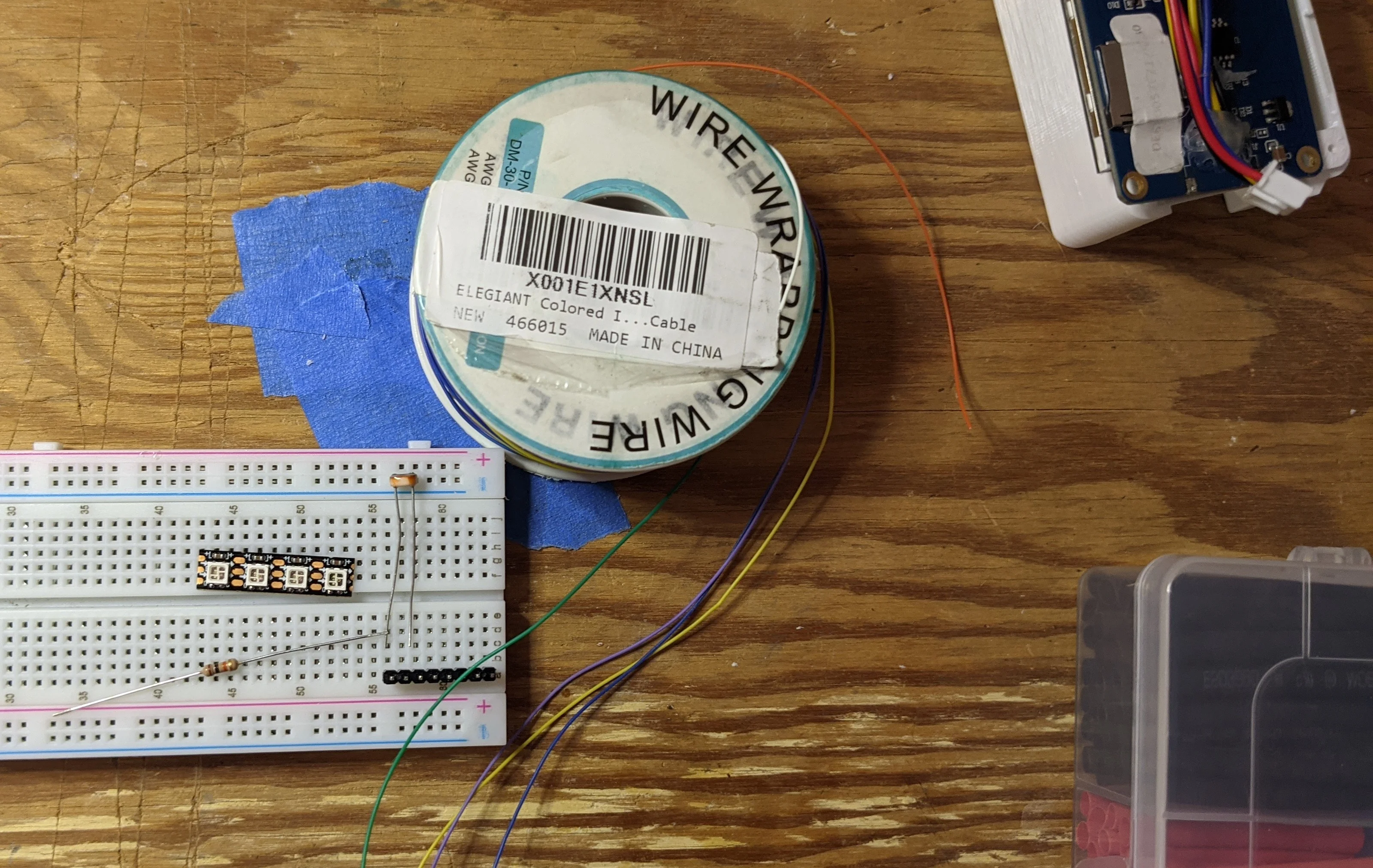
All the components needed for assembly
Note: Where possible, I’ve used commission links. The links don’t raise the price of any item, they simply let the retailer know that I’m the reason for your business. In return, I get a small cut of your purchase as a ’thanks’ from the retailer. If you’re not comfortable with that, you can use a URL unwinding service to get the ‘raw’ product link and drop the attribution/commission part.
Brass inserts
The original instructions suggest using glue to secure the brass inserts to the face plate, but I suggest using either a lighter or a very fine tip soldering iron to heat up the brass insert. A hot insert will melt the surrounding plastic which will make for a much stronger joint. The modified version of the HASP face plate used in this guide intentionally features holes slightly too small for the brass inserts so glue won’t be enough.
Fully insert the 20mm screw into the brass insert, use pliers to grasp the screw and apply heat with a lighter for a few seconds and then insert into the face plate. Make sure that the screw is completely inserted into the insert so that molten plastic can’t flow into the insert. If molten plastic enters and cools on the threads, it will be rather difficult to later screw things together!
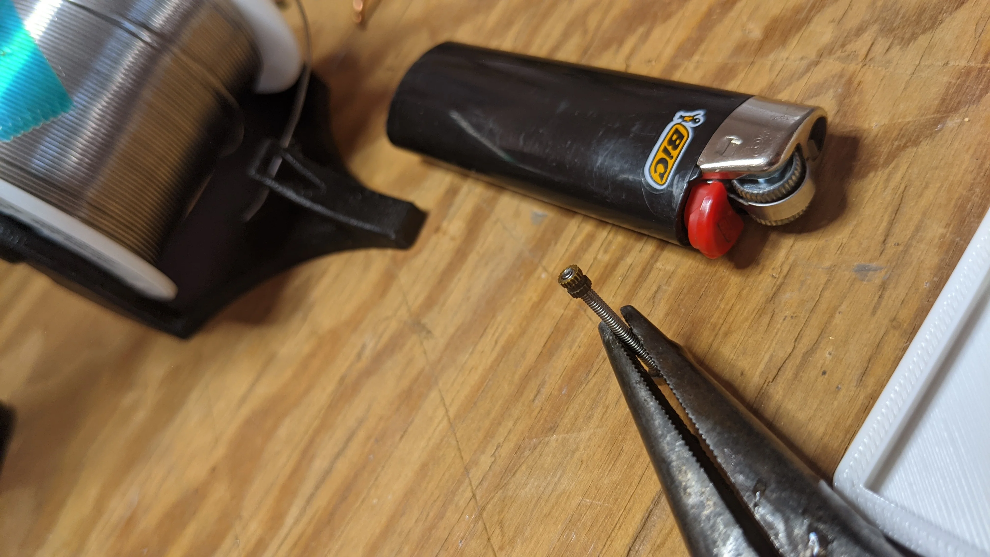
Molten plastic can't flow into a filled insert
As the inserts cool, you’ll have a few seconds to make adjustments to their orientation before they become fixed. Make sure that each screw is vertical and cool to the touch before moving on to the wiring harness.
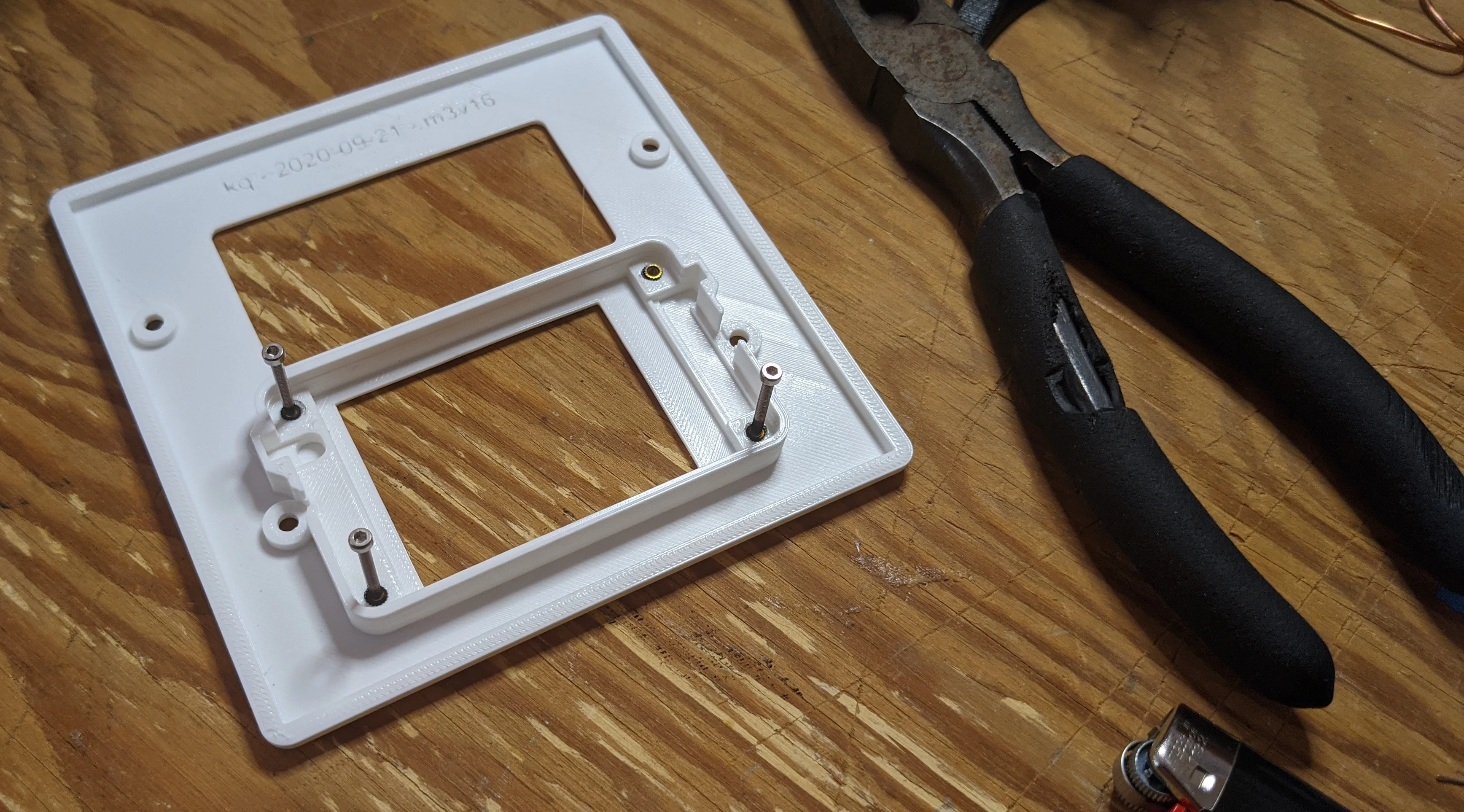
screws make it easy to perform final alignment on inserts and act as a heatsink
Wire Harness
There are only six wires for the two components and the LED tape is the only component where polarity matters. A table mapping each pin on the HASP PCB to each component lead is below.
| HASP PCB Pin | Component |
|---|---|
| GND | LED Tape, 10KΩ resistor |
| +5V | LED Tape VCC in |
| +3.3V | LDR |
| A0 | LDR & 10KΩ resistor junction |
| D0 | N/A |
| D1 | LED Tape CLK/DTA in |
| D2 | N/A |
| DBG | N/A |
You are strongly encouraged to test / check your work after each step with a simple multimeter. Complete assembly involves irreversible steps, like shrinking HST. If you make a mistake, it’s best to catch it before ‘finalizing’ things as you’re almost certainly going to have to destroy the component and or wiring harness to repair it.
Additionally, you can flash my modified HASP firmware to a fully assembled HASP device and use that as a testing device. On boot up, the modified firmware briefly flashes each LED in sequence. About every 10 seconds after boot, the LDR value will be read and published to MQTT. Cover the LDR with your hand and check your MQTT broker or HA to confirm that the value changes significantly between exposed and covered states.
LDR
Fit the LDR into the face plate and position the leads in the channel under and to the top of the LCD PCB. Then trim the excess length off of the LDR leads so that they extend ‘beyond’ the LCD by about 8mm or so.
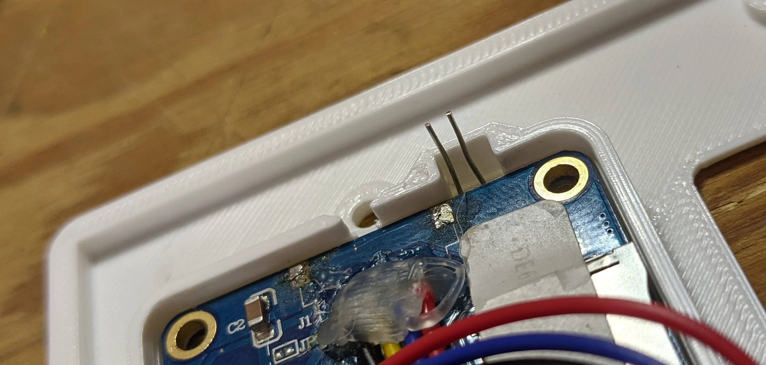
LDR under the LCD w/ trimmed leads...
Remove the LDR from the face plate and straighten the leads out. Lay the LDR, resistor, and wire out as shown below. Use this time to cut the HST down to size so everything but the leg of the LDR that joins the resistor can be covered. Note: the leads on the resistor have also been trimmed down to ~15mm to better fit.
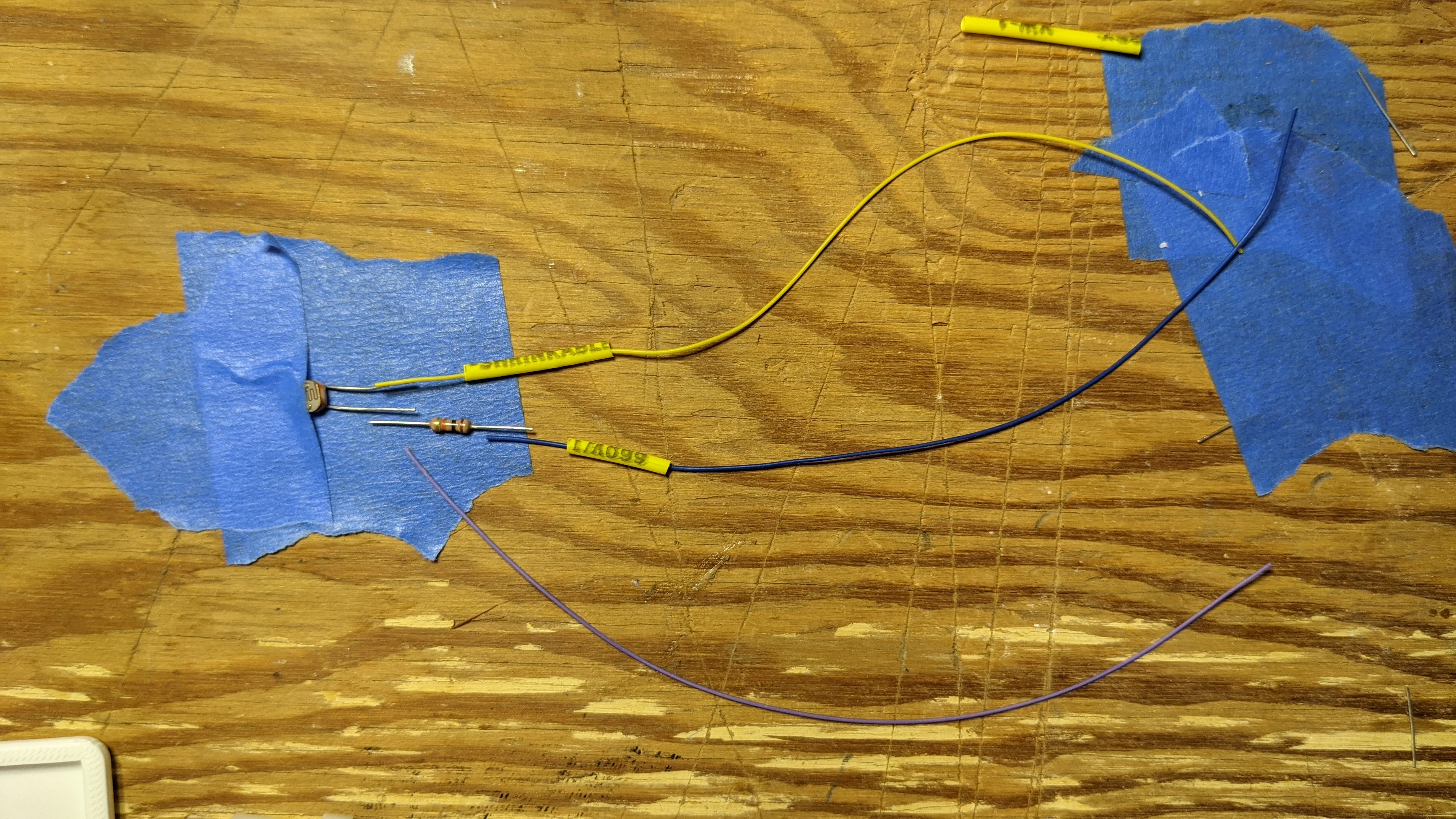
rough layout of LDR harness
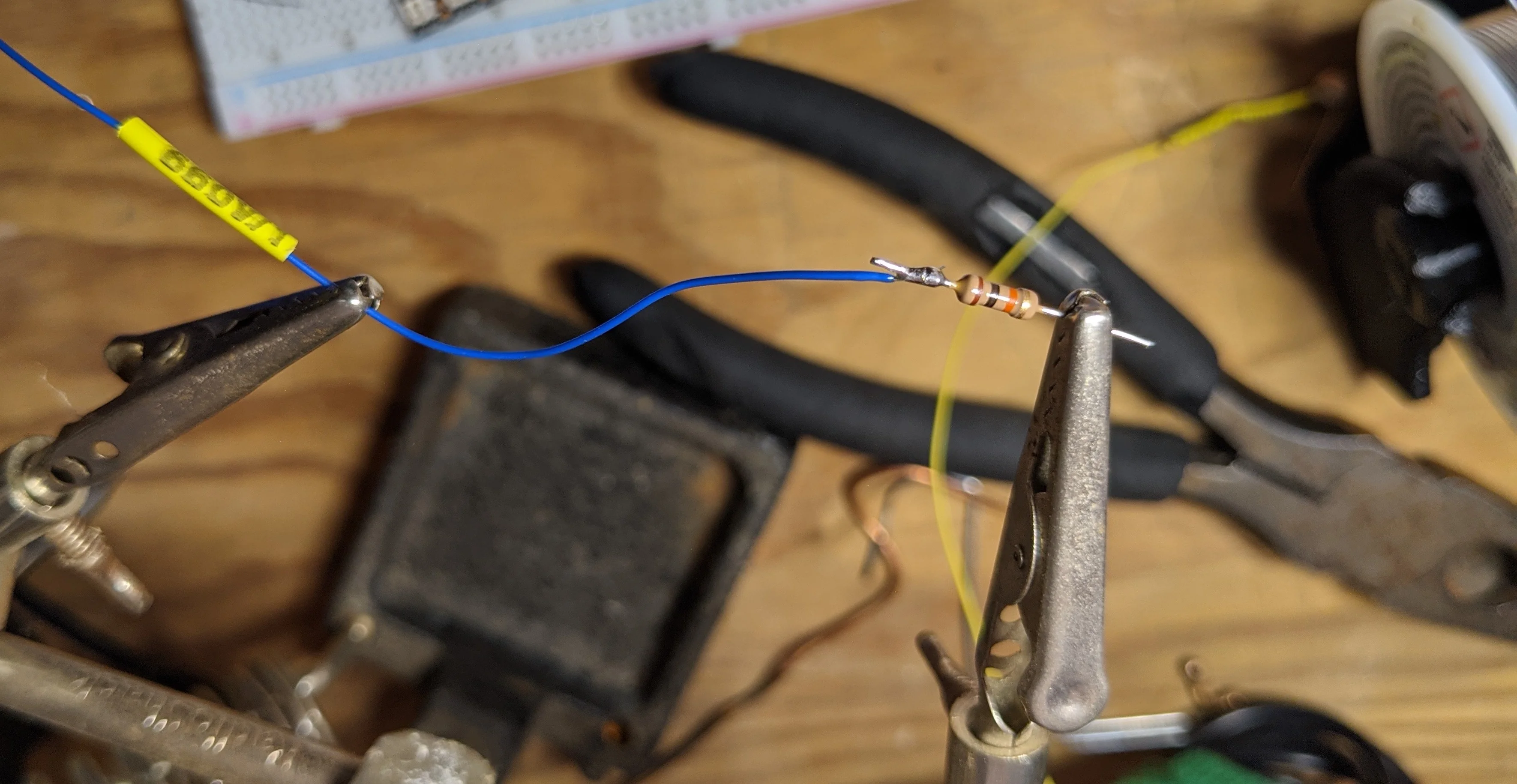
It’s probably going to be easiest to start with the ‘supply’ wire which runs directly from the HASP PCB’s +3.3v pin to the LDR. As space is exceedingly tight, there is no room for overly large solder joints. Carefully wrap the wire around the lead and apply just enough solder to make good electrical contact. Once the supply wire has been soldered to the LDR, affix the HST so the entirety of the lead and solder joint are protected.

strip ~1cm off the end of the wire, wrap around the lead, then solder
Repeat the same procedure with the lead of the resistor that will go directly to the ground. Affix the HST after the solder joint has cooled.
No room for mechanically strong solder joints
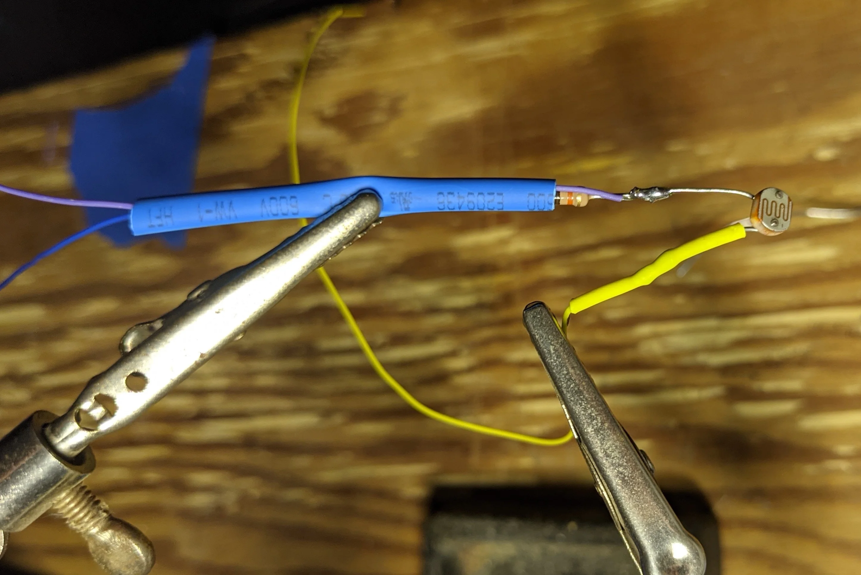
Use the same ‘wrap’ technique with the remaining leads from the LDR and the resistor. Apply just enough solder for good electrical contact between the signal wire and the two leads of the LDR and resistor.
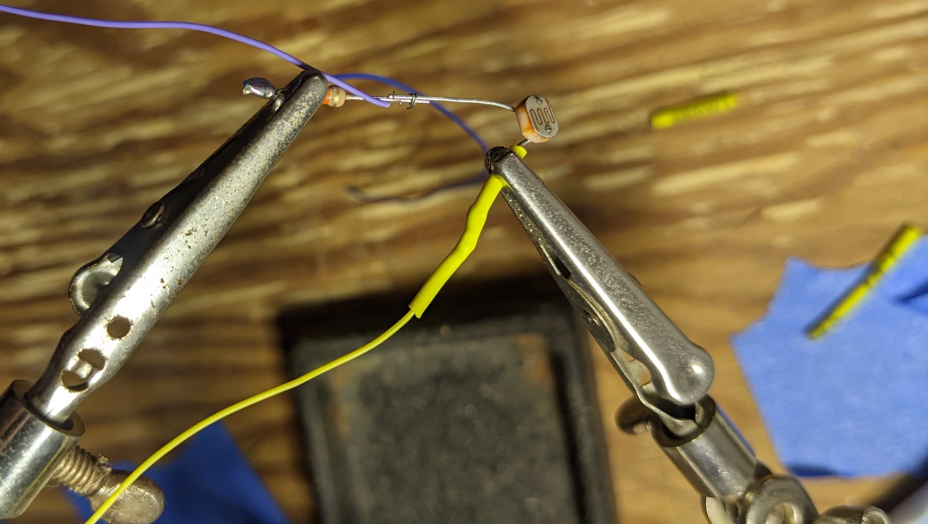
same wrapping technique, just with two leads this time
After the solder joint cools, cover the entire LDR/Resistor assembly in HST so there is no exposed wire or component lead.
get everything nicely protected behind HST
Set the LDR component aside for now and move on to the LED tape.
LEDs
If you’ve not already trimmed the LED tape to fit in the face plate, do so now. Leave yourself as much room as needed to solder on the one side where you’ll need to feed power and data in.
The LED tape has incredibly small pads so take your time on this. You have about 5 cubic millimeters total for the three solder joints on the LED tape. Solder just enough for electrical contact, there will be no significant mechanical stress. Note: The arrows printed on the strip point in the direction of data flow; combined with the off-center placement of the LED packages, there is only one way to properly install the LED tape in the decor plate.
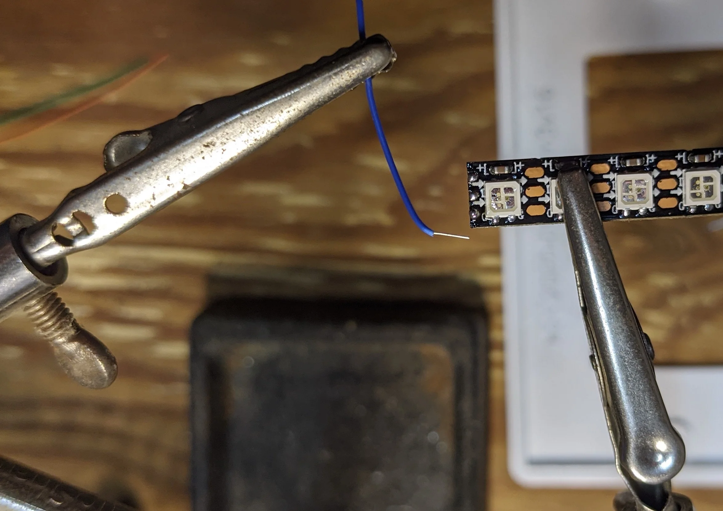
know which way the LED tape wires will need to point to make it into the 'channel' prior to soldering
After soldering the power, signal and ground wires, flatten them and gently shape them so they align and flow into the channel on the face plate in a manner similar to the LDR. For a bit of mechanical robustness, consider braiding the wires together.
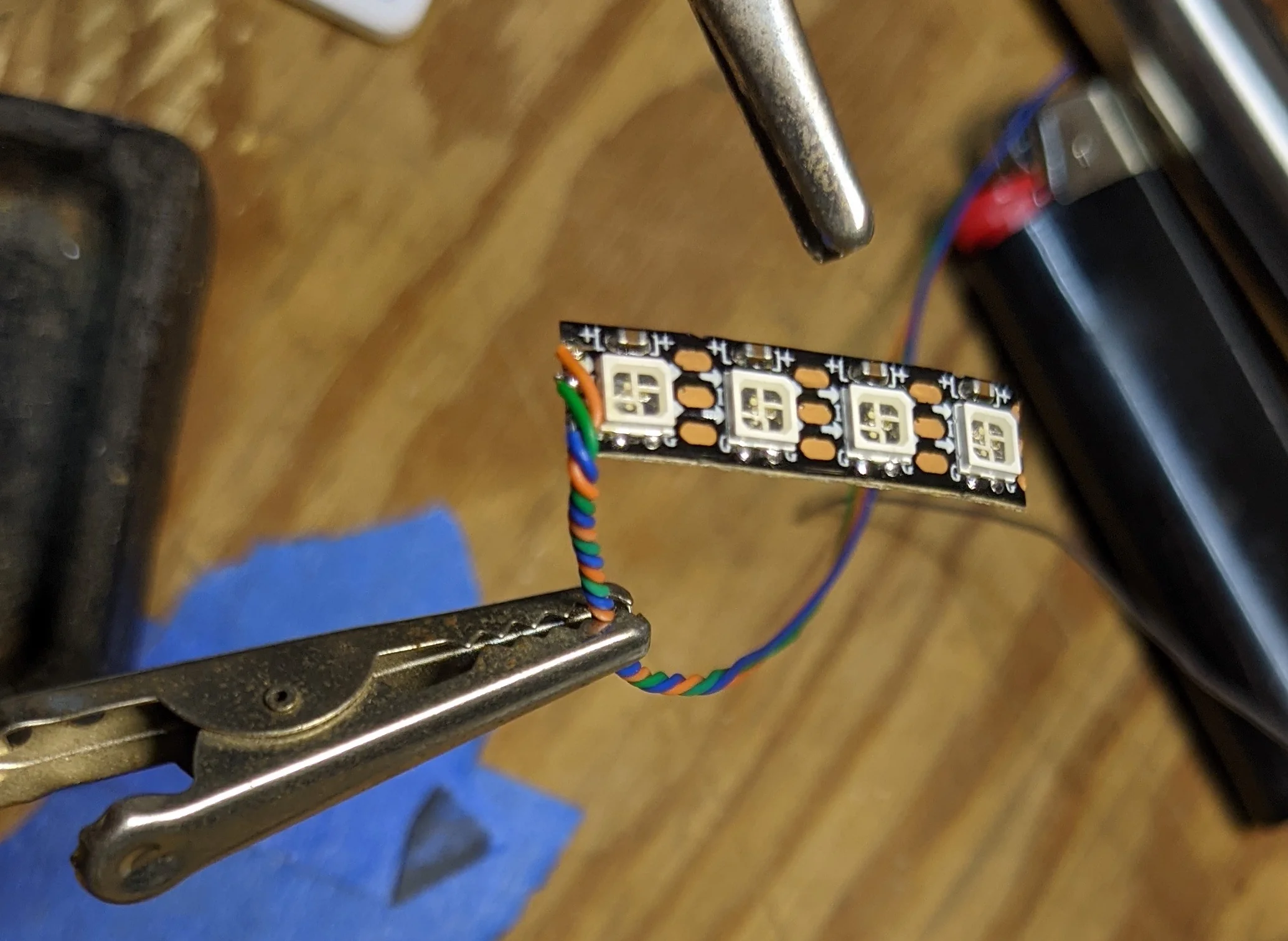
twist the wires together for a more compact and robust cable
Pin Header
After soldering wires onto the two components, all that’s left is soldering the wires to the correct pins on the pin header.
One at a time, carefully take the pins out of the plastic ‘frame’. This is to prevent the heat from the soldering and HST steps from melting the plastic. Consider marking the pin with the location of the ‘frame’ so you don’t take up too much room with the solder joint. You will need the ‘business end’ of the pin to make good contact with the socket on the HASP board; this is quite difficult if most of the pin can’t be slid through the ‘frame’ because of an excessively large solder joint!
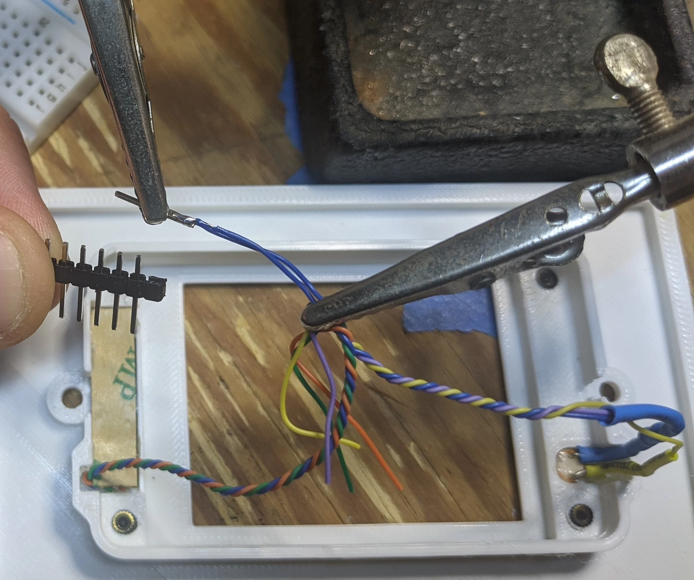
remove the pin from the plastic 'frame' and carefully solder the wires to the pins
Make sure that HST is on the wire(s) before soldering! After the solder joint cools, slip the HST over the solder joint and apply heat until the joint is covered. Repeat this process for the remaining pins. There will be three ‘unused’ pins that you can just ignore.
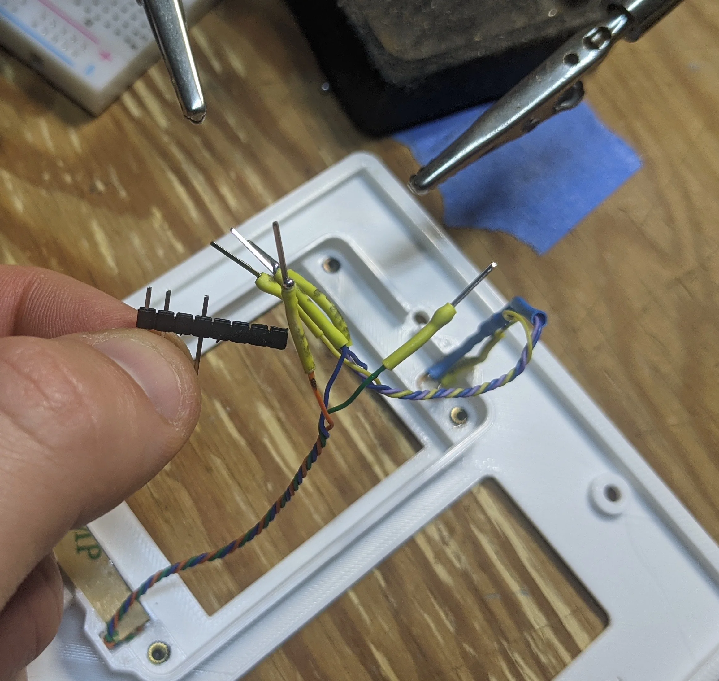
A few pins are not needed
When all the wires have been soldered and covered, you’ll have something that looks like this:
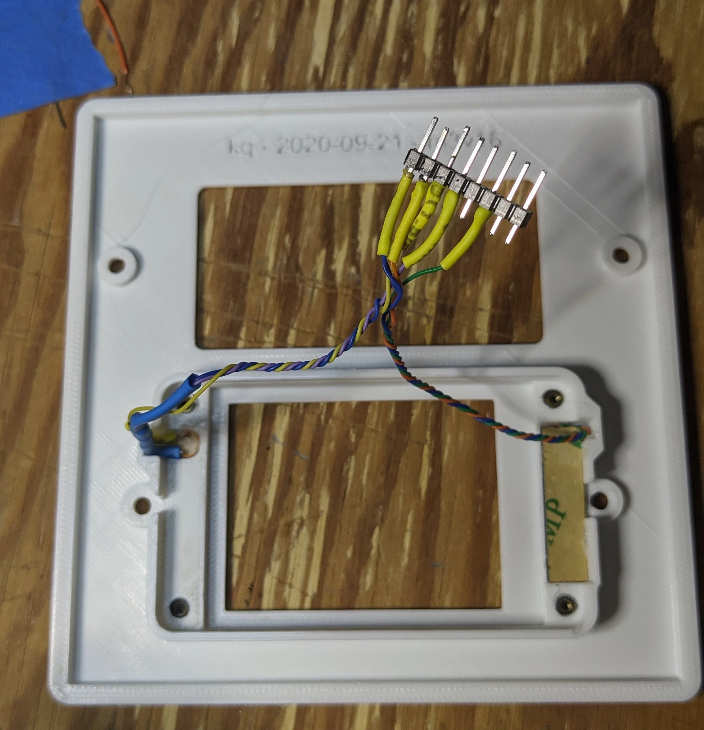
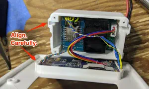
Double check electrical connections and then combine the PCB, enclosure, plate and harness. Carefully align the ‘channels’ for LDR and LED wires:

Align and ensure no pinched wires!
Printing
In the electrical boxes there’s absolutely no room to spare, so all parts are designed to fit together with very tight clearances. Print as slow as you need to in order too achieve very good dimensional accuracy. Like with the brass inserts, the various screw holes are intentionally undersized for better thread engagement.
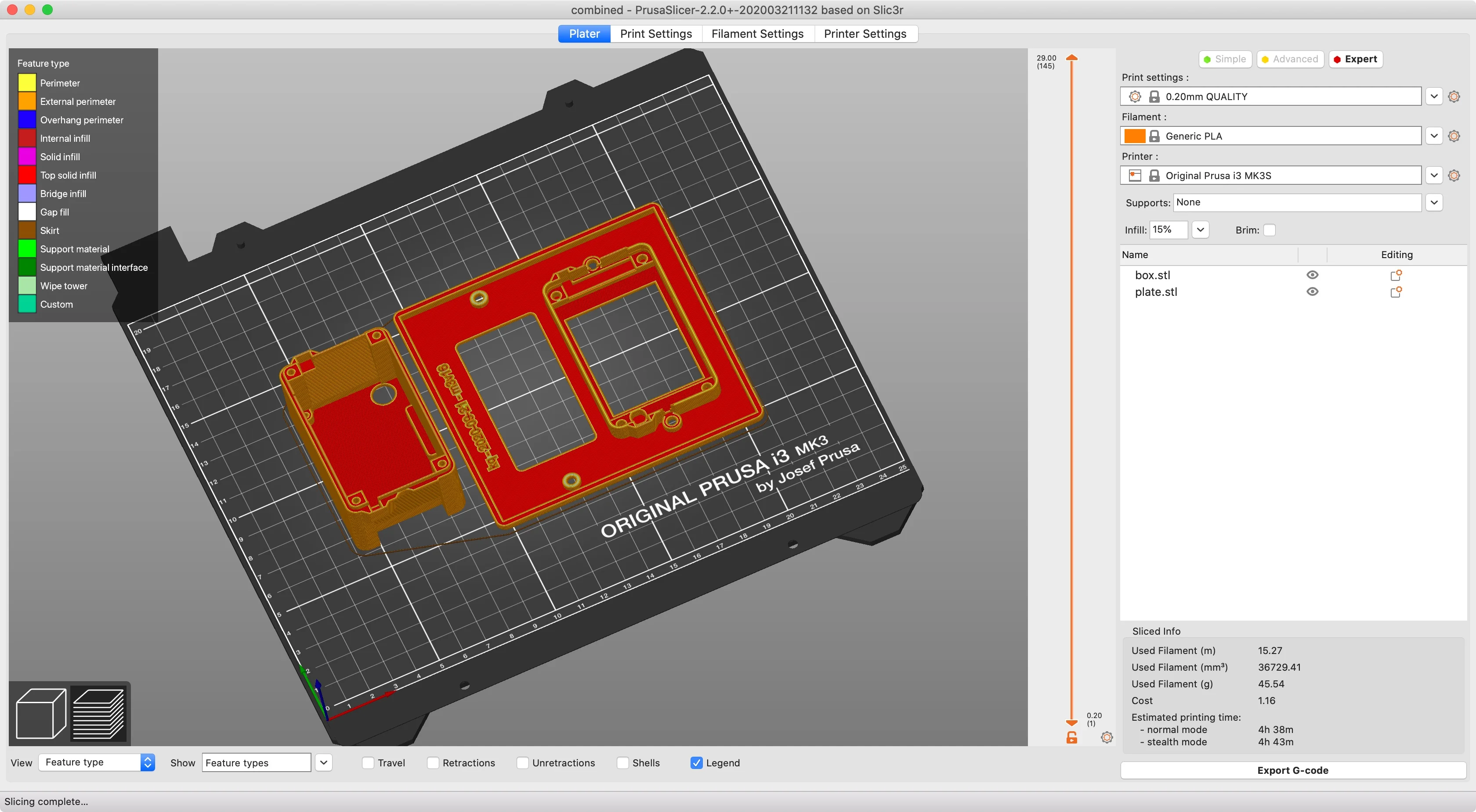
The obvious orientation is the best, no supports needed
The HASP does run a bit warm, but not any warmer than other smart switches with similar form-factor. PLA will likely be fine unless you in tend to deploy the HASP in a particularly hot location.
Thermals
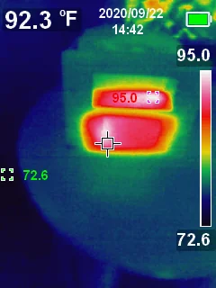
In testing, the parts of the HASP ran ~20º above ambient. Most of that heat comes from the small AC->DC converter and the LCD. Surprisingly, the ESP8266 does not emit that much heat. Overall, nothing particularly alarming, especially when the HASP is deployed into a larger multi-gang electrical box with with plenty of air to radiate heat into. Apologies in advance for the mixed ºC/ºF units.
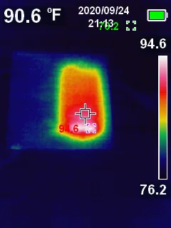
HASP removed from electrical box, heat from the AC-DC converter radiating through the enclosure similar to first picture, parts inside enclosure radiate heat through the enclosure, bringing it to about 20 degrees above ambient temperature there are clear hot-spots on the enclosure that match up with the location of the ESP and the AC-DC converter Less heat is radiated through the front of the HASP; the LCD backlight and embedded LEDs are clearly the warmest components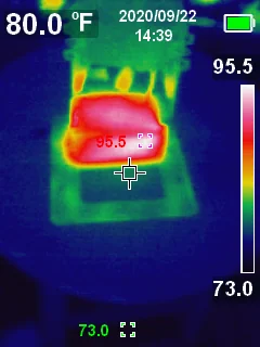

The tiny PNP transistor that toggles the LCD power is the hottest component, by far. Everything else has a relatively consistent temperature:
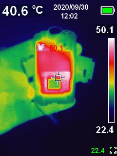
PNP Transistor is clearly warmest internal component, ESP8266 cooler than expected
When installed in wall, the HASP is radiating heat into the electrical box and through neighboring switches:
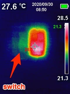
a little bit of ambient heat radiating through the gap between LCD and switch as well as through the switch
Future work
I did accomplish my two main goals:
- Ambient light sensor for more responsive backlight control
- HomeSeer-like LEDs for additional information display
However, there’s a few aspects of the HASP that i’d like to further improve:
Increased automatic configuration w/ the HASP. There’s still a non-trivial amount of work required to set up a HASP with Home Assistant. The HASP device has many different attributes that could be exposed to Home Assistant automatically. E.G.: The HASP will periodically check for a firmware update; the HASP should configure Home Assistant with a
binary_sensorthat indicates if there’s a firmware update available.Some of the automations that live in Home Assistant to manage button presses / update screen content could probably be re-factored down to a few generic scripts and services.
The display uses a resistive matrix to detect touch events. Resistive screens, while cheap, are a bit finnicky and inferior to the more consistent and precise capacitive touch screen tech. If Nextion ever makes a capacitive version of the NX3224T024, then it would be an instant upgrade!
Similarly, the viewing angle on the LCD is… not great. The HASP, like most light switches, is at a convenient height for hands… not eyes. If you’re standing relatively close to the HASP, you’ll be looking down at the screen with quite a steep angle. Depending on the current screen brightness and colors, this may result in a washed out and illegible screen.
Better LED diffusion. There’s not a lot of space for light pipes or similar, but I would like to find a better way of diffusing the LEDs. Or even to fit a masking layer between the LEDs and the plate, so the effect would be akin to a back-lit silhouette.
Effects for the LEDs. Right now, the LEDs only support on/off/brightness commands. Their ability to passively indicate information would be enhanced if Home Assistant could send ’effect’ commands, too. E.G.: Rather than HA having to send a constant stream of color/brightness commands to fade between blue, green, yellow, purple, simply send a
fade(2s) blue, green, yellow, purplecommand.There’s plenty of spare room on the HASP PCB for the 10KΩ resistor. This would simplify the creation of the wiring harness. I’ve been meaning to learn KiKad, this might be a very gentle way to start learning it. 🤔
Enclose the LED tape 100% inside the HASP. This version works well and the small ‘hole’ in the enclosure. I don’t think there’s any safety concern w/ the current design, but I’d still like to have the low voltage stuff 100% blocked off from thee electrical box…
Files
For archive / posterity, all source files are included here. Unless otherwise explicitly stated otherwise, all files below are licensed as Creative Commons Attribution-NonCommercial-ShareAlike (CC BY-NC-SA).
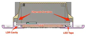
Section analysis from f360 showing small channels around the LCD for wires to LDR and LEDs 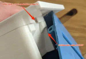
The only way to fit the HASP in my 2-gang electric boxes is to cut out a small section 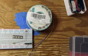
All the components needed for assembly 
Molten plastic can't flow into a filled insert 
screws make it easy to perform final alignment on inserts and act as a heatsink 
LDR under the LCD w/ trimmed leads... 
rough layout of LDR harness 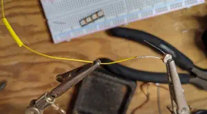
strip ~1cm off the end of the wire, wrap around the lead, then solder 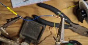
No room for mechanically strong solder joints 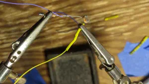
same wrapping technique, just with two leads this time 
get everything nicely protected behind HST 
know which way the LED tape wires will need to point to make it into the 'channel' prior to soldering 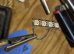
twist the wires together for a more compact and robust cable 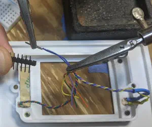
remove the pin from the plastic 'frame' and carefully solder the wires to the pins 
A few pins are not needed 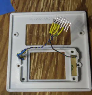
Align and ensure no pinched wires! 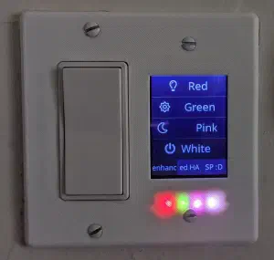
If the LEDs weren't on, you'd never know they were there 😊 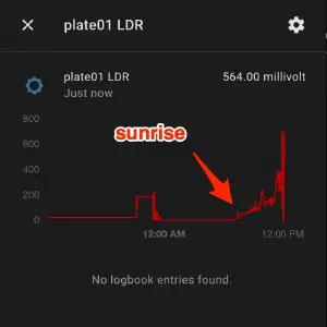
ignore the spikes just before noon, those are due to to testing with a flash light - models/box.step: step file
- models/box.stl: stl file
- models/combined.3mf: 3mf file
- models/combined.step: step file
- models/enhanced-HASP.f3z:
- models/plate.step: step file
- models/plate.stl: stl file
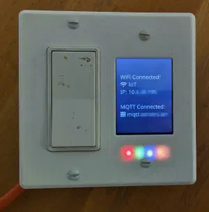
Ignore the dirt on the switch. Notice how you can't tell there's an LDR beneath the surface 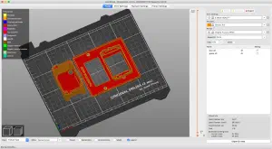
The obvious orientation is the best, no supports needed 
HASP removed from electrical box, heat from the AC-DC converter radiating through the enclosure 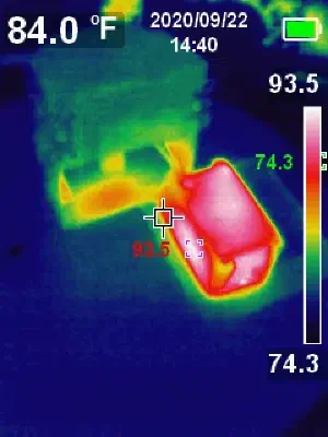
similar to first picture, parts inside enclosure radiate heat through the enclosure, bringing it to about 20 degrees above ambient temperature 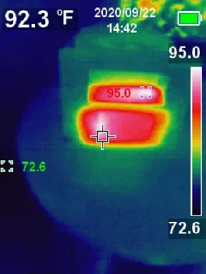
there are clear hot-spots on the enclosure that match up with the location of the ESP and the AC-DC converter 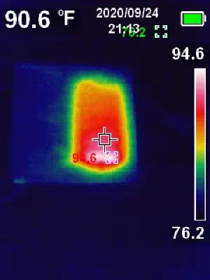
Less heat is radiated through the front of the HASP; the LCD backlight and embedded LEDs are clearly the warmest components 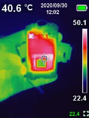
PNP Transistor is clearly warmest internal component, ESP8266 cooler than expected 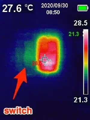
a little bit of ambient heat radiating through the gap between LCD and switch as well as through the switch 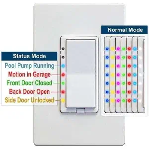
HomeSeer's WS200 has a delightful innovation... RGB LEDs!