electronics lab: enhanced psu
While doing the PoE related testing for this incident, it occurred to me that I never got around to sharing the files for a small modification to the popular RD6006 PSU.
While drafting this post, I discovered that there appears to be a newer version of the RD6006: the 6012. As far as I can tell, they’re in the same ‘family’ and have the same dimensions so the CAD and related model files below should work w/ the RD6012 just as they do w/ the 6006, but i can only ‘guarantee’ that the CAD and related model files below will work with the RD6006.
A version of this post appears on prusaprinters and thingiverse
What
A small enclosure for a PoE injector and QC 3.0 charger designed to sit on top of the RD6012 PSU ‘kit’ sold all over aliexpress and banggood.
Assembled, it looks like this:
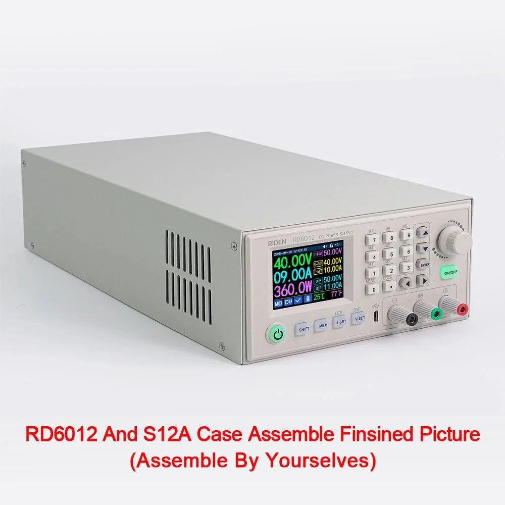
As seen on AliExpress
The RD6006 is incredibly versatile, but can only supply power for about 85% of the devices that make their way onto my ‘healing’ bench. I wasn’t keen on taking up more valuable space with a device dedicated to PoE injection so finding a way to mod one into the PSU seemed like a good idea. Similarly, adding a versatile USB port seemed like a no-brainer as my favorite soldering iron is powered via QuickCharge 3.
Three useful bench tools, one footprint, one consumed power outlet. What’s not to love?
Printing
There are two components for this build:
- the ‘plate’ which rests on the top of the PSU case and has small ‘fences’ to fix the circuit boards in place. It’s the ‘salmon’ colored component
- the ’lid’ is the (mostly) transparent yellow component which holds the auxiliary power supplies (pink components) in place and keeps all voltages away from people.
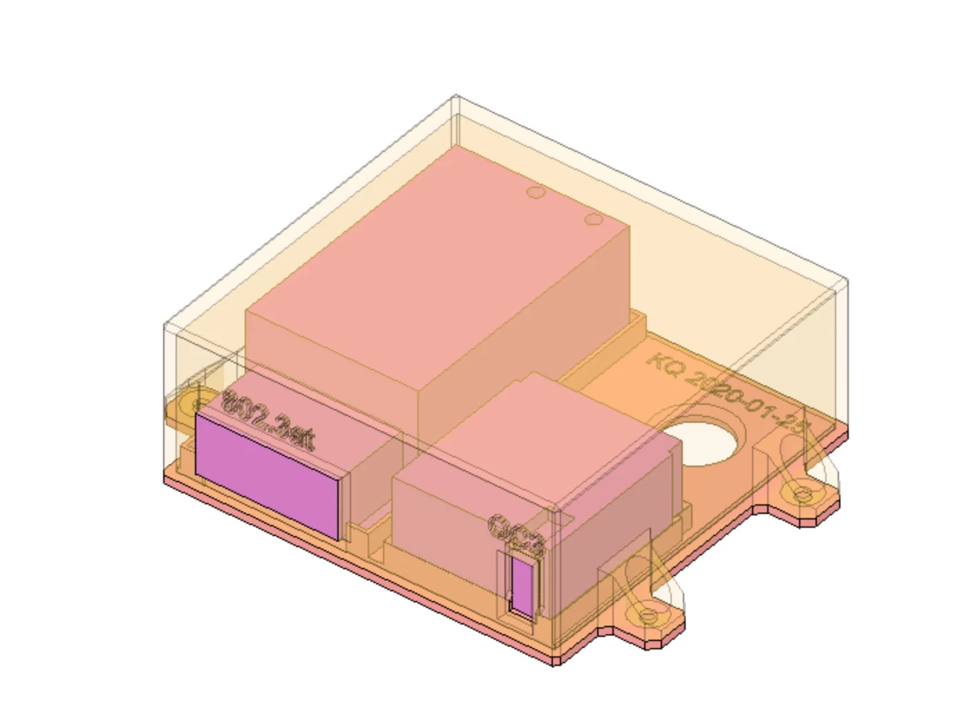
Colorized Components
Relevant components, colored in F360
I used black PETG, but any material and at least 10% infill should be fine. Tune the layer height to taste.
The ‘plate’ does not need any supports nor does the lid if printed in the suggested print orientation shown below :point_down:. I printed with settings optimized for speed so there was minimal sagging, but nothing substantial. What little there was didn’t interfere with clearance of any other internal component and was completely hidden.
If you’re not comfortable with bridging long distances, you can optionally enforce support material from the build plate to the top of the lid or flip the lid upside down and use supports for the four feet where the screws go. Because any sagging would be hidden inside,

suggested print orientation
Components
In addition to the miscellaneous wire and crimp connectors, there are two components used in this design:
Assembly
I don’t have any pictures from the assembly :disappointed:, but it’s not particularly difficult to figure out from the attached pictures. In general, the steps to take are:
- Print everything and clean up the parts as needed
- de-shell the PoE injector and QC3 charger. A plastic pry-tool or a few flat-head screwdrivers will help here!
- desolder the existing mains connections from both modules and solder on new ones. The new ones don’t need to be long, just a bit longer than the leads that came on the module PCBs!
- disconnect power from the assembled PSU and remove the case cover
- place the ‘plate’ onto the top of the PSU and use a pencil to mark all 5 holes on the cover
- remove the plate, drill out all 5 holes and use a file to smooth down any sharp edges on the big hole as that’s where the mains wires will go. A burr poking through insulation means the case may become energized @ mains voltages! :boom: :skull:
- crimp connectors onto wires and attach to the mains supply after the switch and fuse!
- place the ‘plate’ back onto the PSU cover
- run the wires through the new hole in the top of the PSU case and through the hole in the ‘plate’
- add the PoE injector and QC3 module to the plate
- join the mains leads to the module leads. I used Wago connectors, but simple wirenuts or a screw terminal block will work.
- Use M3 screws to secure the lid to the plate and the PSU. I intentionally drilled the holes slightly too small so the screws would thread against the case. Not ideal, but works absolutely fine for something that’s not load-bearing or going to be repeatedly re-screwed.
- re-connect the IEC power connector and power on
- monitor for sounds and smells that indicate you screwed up. begin testing PoE and USB port for proper power.
Just prior to seating the ’lid’ you should have something like this:

components seated and wired
When all said and done, you’ll get this:
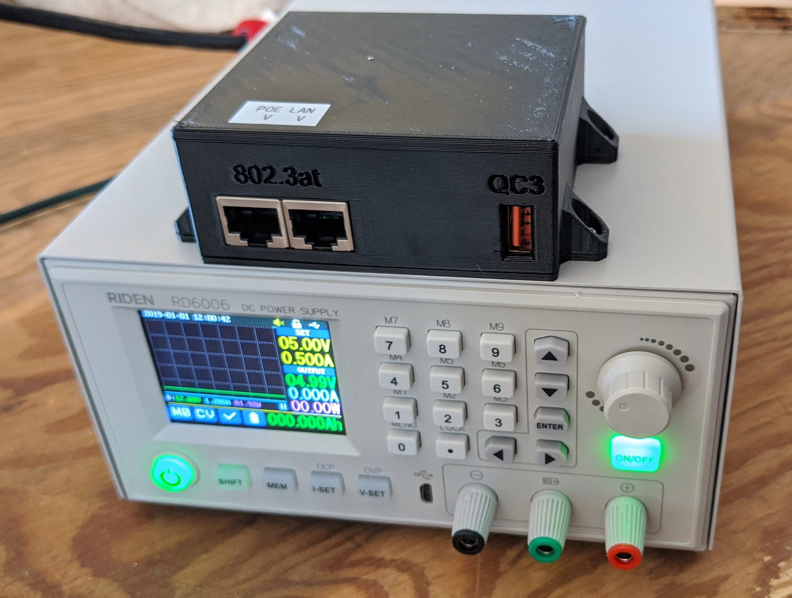
everything assembled and powered up
Files
The f360 file is… a mess. I’m not going to share it here. Contact me if you really want it. The stl and 3mf files are below, though. As you can tell from the initials and date, this project was ‘completed’ awhile ago.
For archive / posterity, all source files are included here. All files are licensed as Creative Commons Attribution-NonCommercial-ShareAlike (CC BY-NC-SA).

everything assembled and powered up 
Relevant components, colored in F360 - models/combined.3mf: 3mf file
- models/lid.stl: stl file
- models/plate.stl: stl file
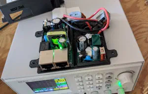
components seated and wired 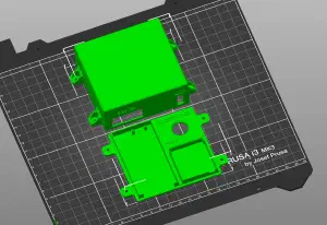
suggested print orientation 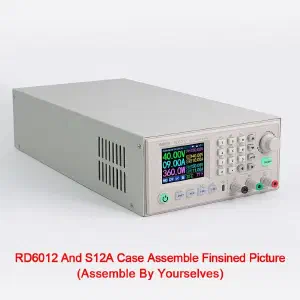
As seen on AliExpress


