ESPHome on dingtian-tech relay modules
This is another one of those quick “I wish that was easier to find when I was googling it” posts.
For a project, I needed a small relay module to switch a few mains loads. I chose this generic looking relay module from AliExpress because it was powered by an ESP32 and featured ethernet connectivity.
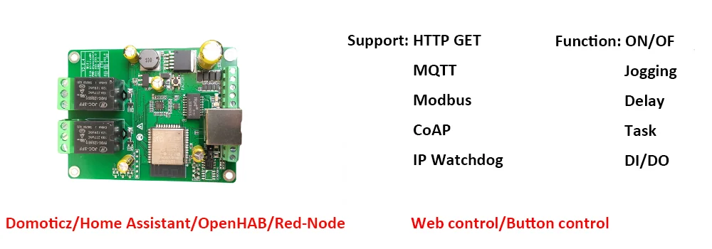
AliExpress is full of generic looking relay modules but this one is branded dingtian-tech
The device came with an obvious programming header right next to the ESP32 so I thought it would be a 5 minute job to flash Tasmota and probe the GPIOs.
N.O.P.E.
This post is a super condensed version of my notes that I’m posting in the off chance that they’re useful for somebody else.
ESP32 Secure Boot
I needed a few more of these modules for another project and before placing my order, I asked about the possibility of getting an “empty” module shipped with no firmware protections set.
The seller told me to place my order and then message them with the order number and a note asking to send relay board with test firmware.
I did just that and a little over two weeks later, I received a module with no protections set!
No matter what I did to flash the ESP32 module, it would always boot loop with output like this:
rst:0x1 (POWERON_RESET),boot:0x7 (DOWNLOAD_BOOT(UART0/UART1/SDIO_REI_REO_V2))␍␊
waiting for download␍␊
<break>
<0xff>ets Jun  8 2016 00:22:57␍␊
I knew that I didn’t brick anything because the ESP would boot right up as soon as i re-flashed the original dump.
Turns out, there’s a few reasons why this might happen but in this case, it’s because secure boot was enabled.
Because at least a decent chunk of the flash dump I took was in plain text, I didn’t thing that there was any flash protection in place but sure enough, at least some of the protection features have been enabled:
❯ espefuse.py summary
Connecting...
Detecting chip type... Unsupported detection protocol, switching and trying again...
Connecting...
Detecting chip type... ESP32
espefuse.py v3.3.1

=== Run "summary" command ===
EFUSE_NAME (Block) Description  = [Meaningful Value] [Readable/Writeable] (Hex Value)
----------------------------------------------------------------------------------------
Calibration fuses:
BLK3_PART_RESERVE (BLOCK0):                        BLOCK3 partially served for ADC calibration data   = False R/W (0b0)
ADC_VREF (BLOCK0):                                 Voltage reference calibration                      = 1114 R/W (0b00010)

Config fuses:
XPD_SDIO_FORCE (BLOCK0):                           Ignore MTDI pin (GPIO12) for VDD_SDIO on reset     = False R/W (0b0)
XPD_SDIO_REG (BLOCK0):                             If XPD_SDIO_FORCE, enable VDD_SDIO reg on reset    = False R/W (0b0)
XPD_SDIO_TIEH (BLOCK0):                            If XPD_SDIO_FORCE & XPD_SDIO_REG                   = 1.8V R/W (0b0)
CLK8M_FREQ (BLOCK0):                               8MHz clock freq override                           = 54 R/W (0x36)
SPI_PAD_CONFIG_CLK (BLOCK0):                       Override SD_CLK pad (GPIO6/SPICLK)                 = 0 R/W (0b00000)
SPI_PAD_CONFIG_Q (BLOCK0):                         Override SD_DATA_0 pad (GPIO7/SPIQ)                = 0 R/W (0b00000)
SPI_PAD_CONFIG_D (BLOCK0):                         Override SD_DATA_1 pad (GPIO8/SPID)                = 0 R/W (0b00000)
SPI_PAD_CONFIG_HD (BLOCK0):                        Override SD_DATA_2 pad (GPIO9/SPIHD)               = 0 R/W (0b00000)
SPI_PAD_CONFIG_CS0 (BLOCK0):                       Override SD_CMD pad (GPIO11/SPICS0)                = 0 R/W (0b00000)
DISABLE_SDIO_HOST (BLOCK0):                        Disable SDIO host                                  = False R/W (0b0)

Efuse fuses:
WR_DIS (BLOCK0):                                   Efuse write disable mask                           = 388 R/W (0x0184)
RD_DIS (BLOCK0):                                   Efuse read disable mask                            = 3 R/W (0x3)
CODING_SCHEME (BLOCK0):                            Efuse variable block length scheme
   = NONE (BLK1-3 len=256 bits) R/W (0b00)
KEY_STATUS (BLOCK0):                               Usage of efuse block 3 (reserved)                  = False R/W (0b0)

Identity fuses:
MAC (BLOCK0):                                      Factory MAC Address
   = 78:21:84:56:b1:50 (CRC 0x6c OK) R/W
MAC_CRC (BLOCK0):                                  CRC8 for factory MAC address                       = 108 R/W (0x6c)
CHIP_VER_REV1 (BLOCK0):                            Silicon Revision 1                                 = True R/W (0b1)
CHIP_VER_REV2 (BLOCK0):                            Silicon Revision 2                                 = False R/W (0b0)
CHIP_VERSION (BLOCK0):                             Reserved for future chip versions                  = 2 R/W (0b10)
CHIP_PACKAGE (BLOCK0):                             Chip package identifier                            = 1 R/W (0b001)
CHIP_PACKAGE_4BIT (BLOCK0):                        Chip package identifier #4bit                      = False R/W (0b0)
MAC_VERSION (BLOCK3):                              Version of the MAC field                           = 0 R/W (0x00)

Security fuses:
FLASH_CRYPT_CNT (BLOCK0):                          Flash encryption mode counter                      = 1 R/- (0b0000001)
UART_DOWNLOAD_DIS (BLOCK0):                        Disable UART download mode (ESP32 rev3 only)       = False R/- (0b0)
FLASH_CRYPT_CONFIG (BLOCK0):                       Flash encryption config (key tweak bits)           = 15 R/W (0xf)
CONSOLE_DEBUG_DISABLE (BLOCK0):                    Disable ROM BASIC interpreter fallback             = True R/W (0b1)
ABS_DONE_0 (BLOCK0):                               Secure boot V1 is enabled for bootloader image     = True R/W (0b1)
ABS_DONE_1 (BLOCK0):                               Secure boot V2 is enabled for bootloader image     = False R/W (0b0)
JTAG_DISABLE (BLOCK0):                             Disable JTAG                                       = True R/W (0b1)
DISABLE_DL_ENCRYPT (BLOCK0):                       Disable flash encryption in UART bootloader        = True R/W (0b1)
DISABLE_DL_DECRYPT (BLOCK0):                       Disable flash decryption in UART bootloader        = True R/W (0b1)
DISABLE_DL_CACHE (BLOCK0):                         Disable flash cache in UART bootloader             = True R/W (0b1)
BLOCK1 (BLOCK1):                                   Flash encryption key
   = ?? ?? ?? ?? ?? ?? ?? ?? ?? ?? ?? ?? ?? ?? ?? ?? ?? ?? ?? ?? ?? ?? ?? ?? ?? ?? ?? ?? ?? ?? ?? ?? -/-
BLOCK2 (BLOCK2):                                   Secure boot key
   = ?? ?? ?? ?? ?? ?? ?? ?? ?? ?? ?? ?? ?? ?? ?? ?? ?? ?? ?? ?? ?? ?? ?? ?? ?? ?? ?? ?? ?? ?? ?? ?? -/-
BLOCK3 (BLOCK3):                                   Variable Block 3
   = 00 00 00 00 00 00 00 00 00 00 00 00 00 00 00 00 00 00 00 00 00 00 00 00 00 00 00 00 00 00 00 00 R/W

Flash voltage (VDD_SDIO) determined by GPIO12 on reset (High for 1.8V, Low/NC for 3.3V).
That’s the first time I’ve ever seen the security settings enabled on cheap IoT gear from China. 🤯
In hindsight, it should have been pretty obvious as the flash dump does not look like a “traditional” ESP flash dump:
❯ binwalk flash_4M.bin

DECIMAL       HEXADECIMAL     DESCRIPTION
--------------------------------------------------------------------------------
1131864       0x114558        AES S-Box
1155516       0x11A1BC        Base64 standard index table
1161148       0x11B7BC        PEM RSA private key
1161212       0x11B7FC        PEM EC private key
1161560       0x11B958        SHA256 hash constants, little endian
1166968       0x11CE78        PEM certificate
2075923       0x1FAD13        mcrypt 2.5 encrypted data, algorithm: "+", keysize: 21964 bytes, mode: "H",
It was late and I was tired so I didn’t bother with trying to reverse engineer the flash dump or trying to figure out if there was a way to disable the protections. Nothing was going to compete with 10 minute to heat-soak and remove the ESP module so I just did that.
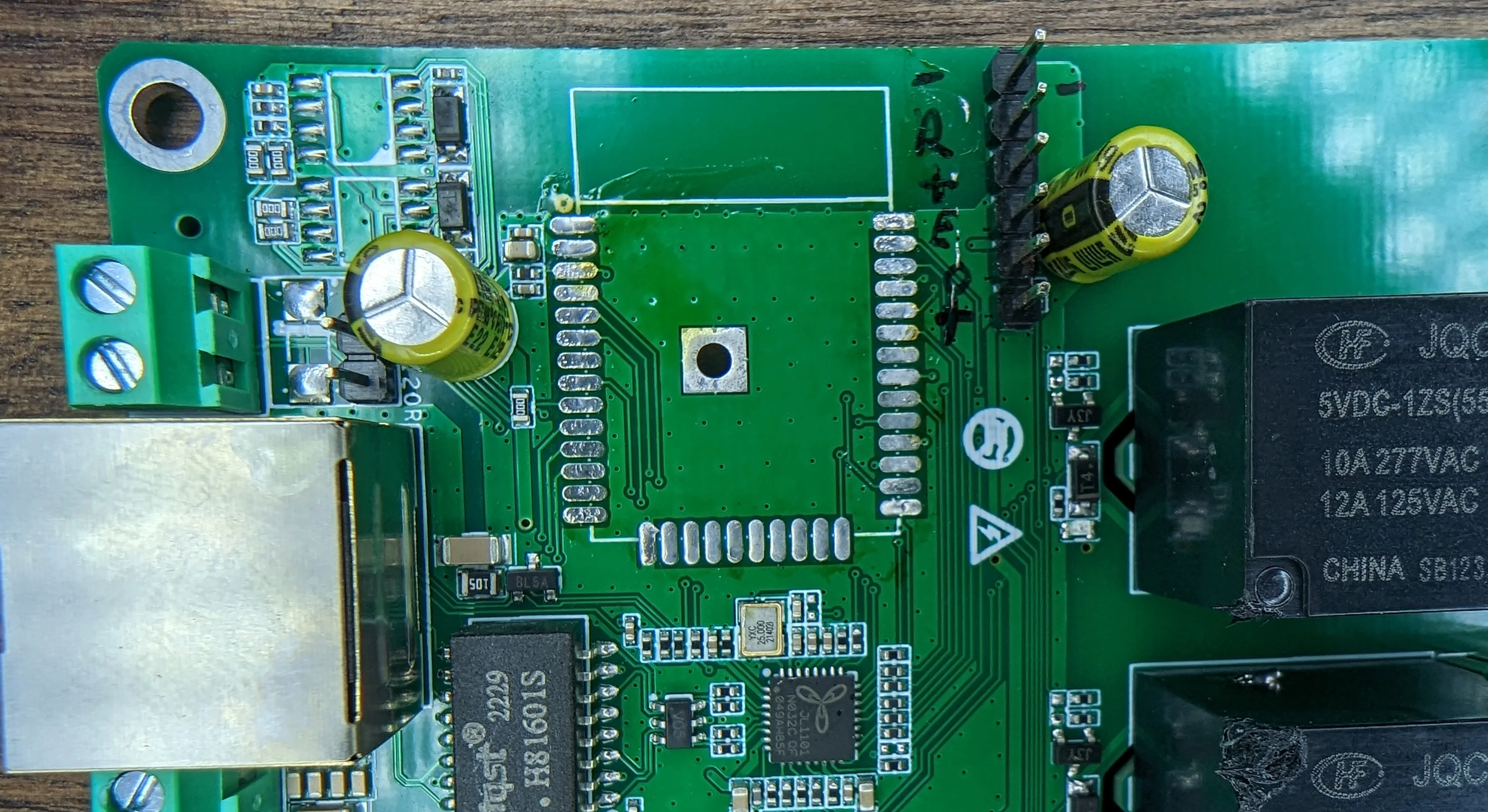
Note the sharpie next to the pin headers. Order is GND, RX, TX, EN, GPIO0, VCC from top to bottom.
And a better look at some of the PCB traces to the ethernet PHY:
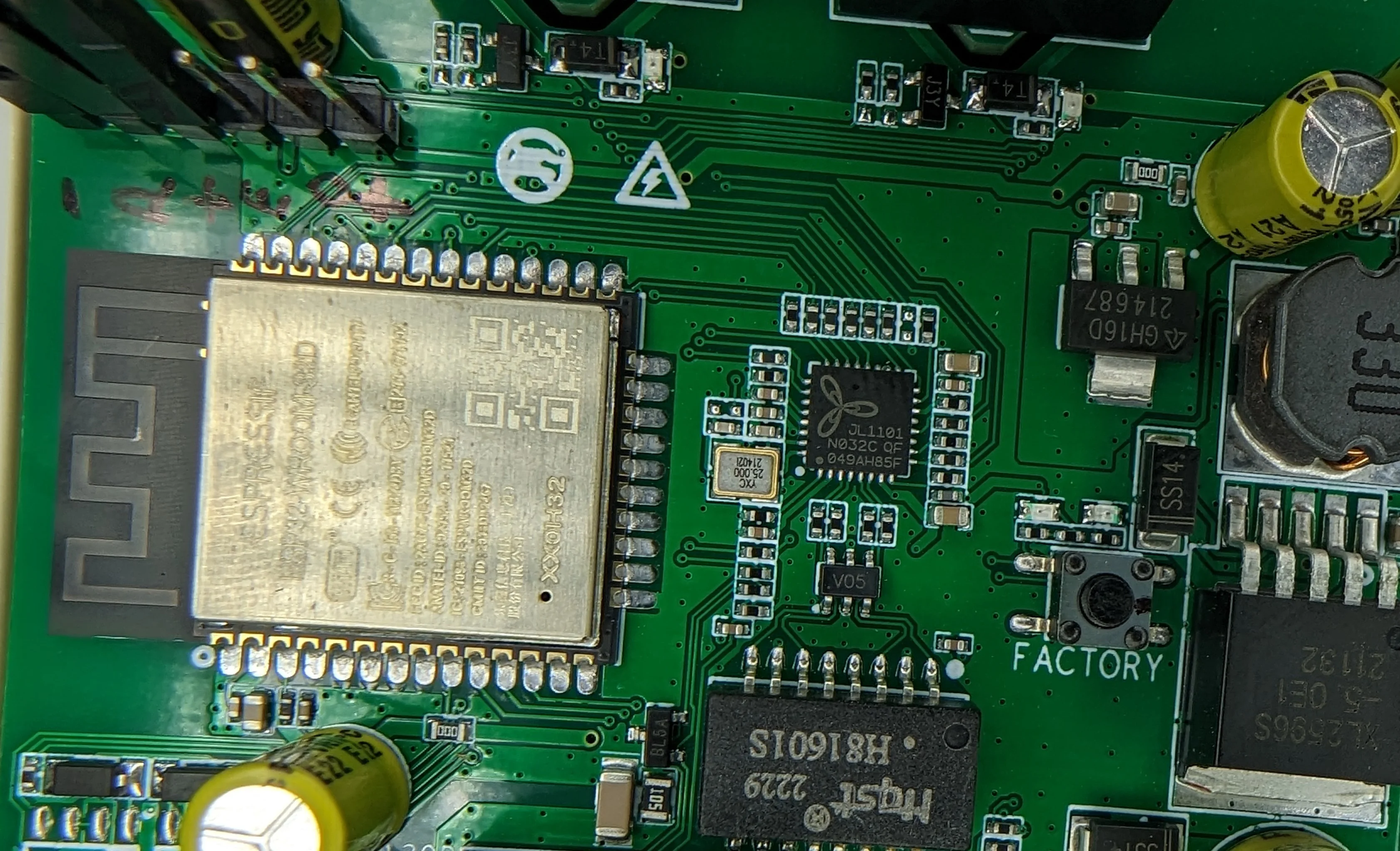
With a “fresh” ESP module installed, figuring out th GPIO assignments wasn’t particularly difficult.
| Function | Pin | Note |
|---|---|---|
| Relay 1 | GPIO2 | – |
| Relay 2 | GPIO16 | – |
| Input 1 | GPIO36 | Normally at 3.3V. Pull to ground to trigger. |
| Input 2 | GPIO39 | Same as Input 1. |
| Input 3 | GPIO34 | This is the FACTORY button. Same as Input 1. |
| LED 1 | GPIO32 | This is the second little red LED next to the FACTORY button. Inverted. |
Tasmota
And here’s the working Tasmota template:
{"NAME":"2chFinal","GPIO":[0,0,224,0,0,0,1,1,0,0,0,0,225,0,0,0,0,0,0,0,0,0,0,0,0,0,0,0,320,0,32,0,160,0,0,161],"FLAG":0,"BASE":1}And visually:
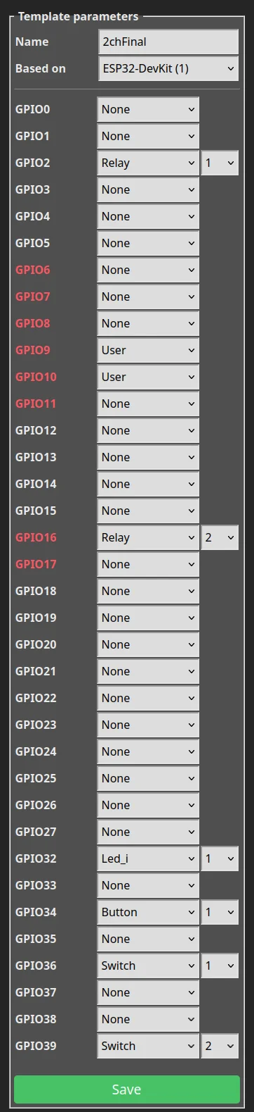
This configuration works even though GPIO34 should be Button_i.
ESPHome
This is a bare-bones config that covers all the core/critical functionality.
esp32:
  # See: https://docs.platformio.org/en/latest/boards/espressif32/esp32dev.html
  board: esp32dev

# Above the "FACTORY" button there are two LEDs. One is wired in series with the switch and the other is controllable via GPIO. Use the second one as a status indicator.
status_led:
  pin:
    number: GPIO32
    inverted: true

ethernet:
  type: JL1101
  mdc_pin: GPIO23
  mdio_pin: GPIO18
  phy_addr: 0
  clk_mode: GPIO17_OUT
  # The PHY chip has a pin labeled TX_EN that goes to GPIO 21 on ESP
  # and the RSTn pin on the phy goes to GPIO0
  ##
  # Datasheet indicates the RSTn should be LOW to disable the phy and default is high
  power_pin: GPIO0


binary_sensor:

# The "factory reset" button
  - platform: gpio
    name: "User Button"
    pin:
      number: GPIO34
      inverted: true

  # The two sets of contacts for manual trigger
  # input is pulled up to 3.3V by default.
  - name: "User Input 1"
    platform: gpio
    pin:
      number: GPIO36
      inverted: true

  - name: "User Input 2"
    platform: gpio
    pin:
      number: GPIO39
      inverted: true

switch:
  - name: "Relay 1"
    platform: gpio
    pin: GPIO2

  - name: "Relay 2"
    platform: gpio
    pin: GPIO16