Arizer XQ2 Teardown
Arizer XQ2 Teardown
A friend of mine reached out and asked me about automating some aspects of their aroma therapy treatment.
The device they’re using for aromatherapy is the Arizer XQ2 and we agreed that integration with their existing Home Assistant setup would be ideal.
I know nothing about aroma therapy but I do suffer from an obsession that compels me to integrate ESPHome with everything…I was intrigued!
At worst, I get a new toy to tear down and at best, I’d be able to deliver a solution that would make their life a little easier.
The plan
First, the bad news.
There’s next to no technical information about the XQ2 online.
The device has no radio connectivity so there’s no FCC filings. There are several reviews of the device online, but none of them tear it down or provide any technical information.
Now, the good news.
The device does have an IR remote control!
It is not difficult to capture the IR signals from the remote and replay them with an ESP32 or similar device. This meant that the likely outcome would be an open-loop control system; building something to to send commands to the device would be trivial but confirming that a particular command had been executed would be tedious at best.
This put us in an awkward position.
After some back and forth, we agreed that closed-loop would be ideal, but open-loop control would be acceptable for their needs given that the device is meant to be used in close proximity to the user and already features a few safety features.
Unless there was some lucky break discovered while tearing down the device, I’d be stuck with emulating the IR remote control. This isn’t ideal, but it also means that there’s virtually no risk that any of the built-in safety features would be bypassed/disabled.
Teardown
The manufacturer has clearly designed this thing to be serviceable!
They have a guide for replacing a common wear item (the ceramic heating element) and it turns out that the rest of the device is just as easy to access.
From the bottom of the device, there are 4 rubber feet that can be removed to reveal 4 screws. Amazingly, these feet are NOT glued in and they have tiny holes in them to allow the screws to be removed without removing the feet! 😚👌.
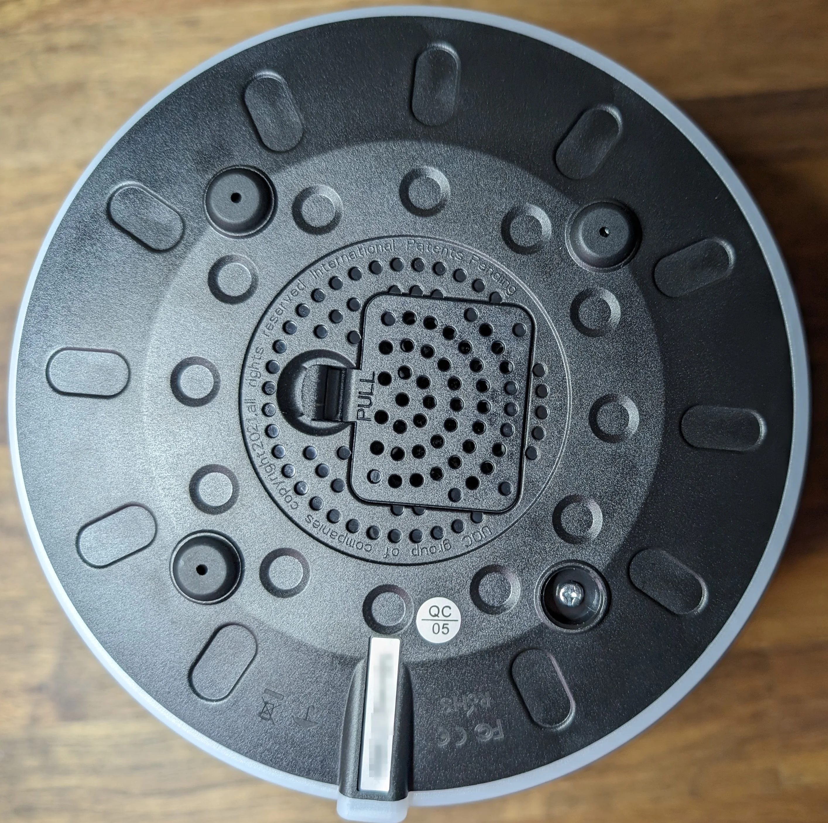
Once the screws are removed, the bottom cover just lifts off. Again, no glue, no clips, no nothing!
This reveals the main PCB. I’ve identified a few of the main ICs below.
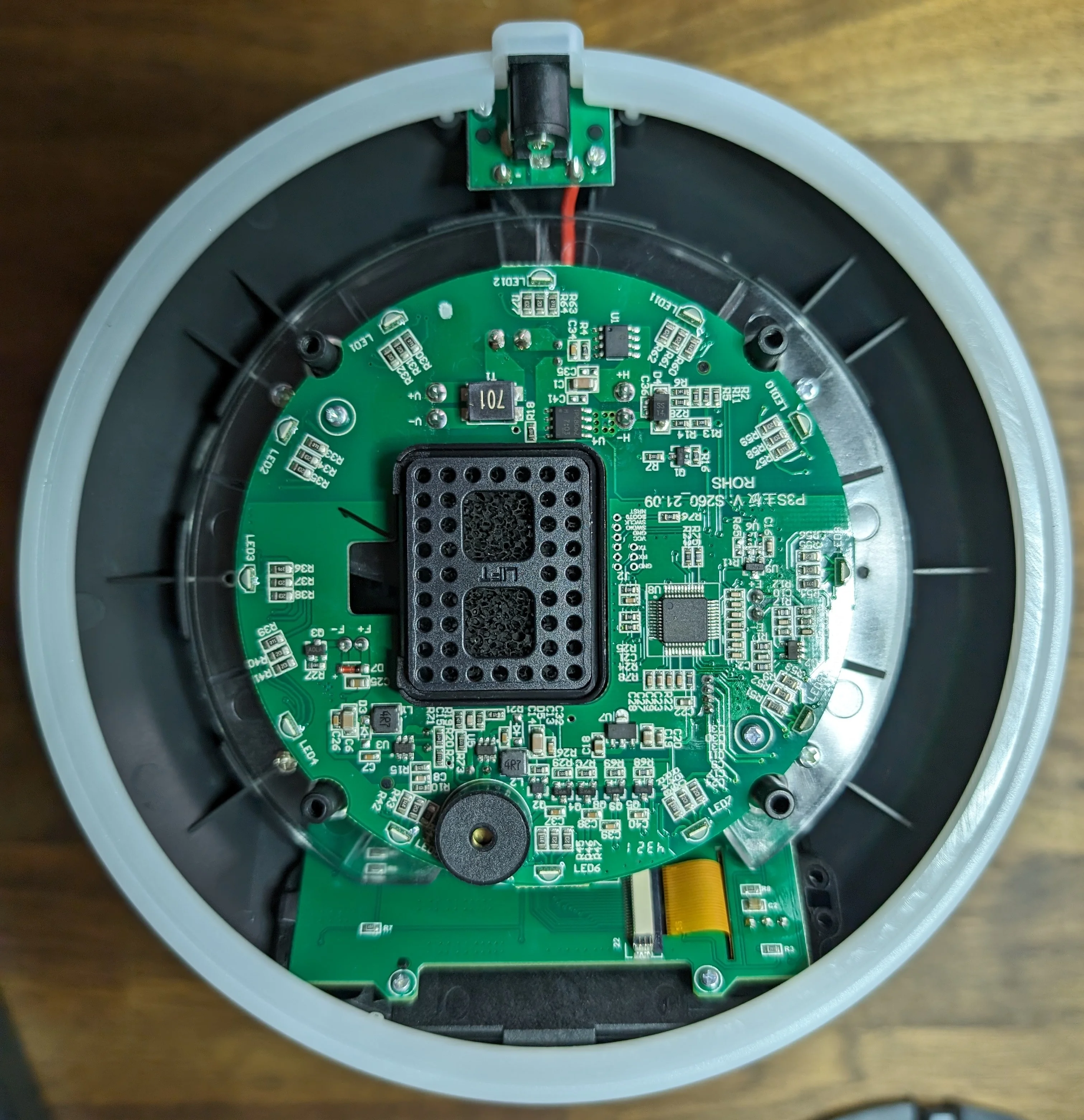
View from the bottom just after removing the panel.
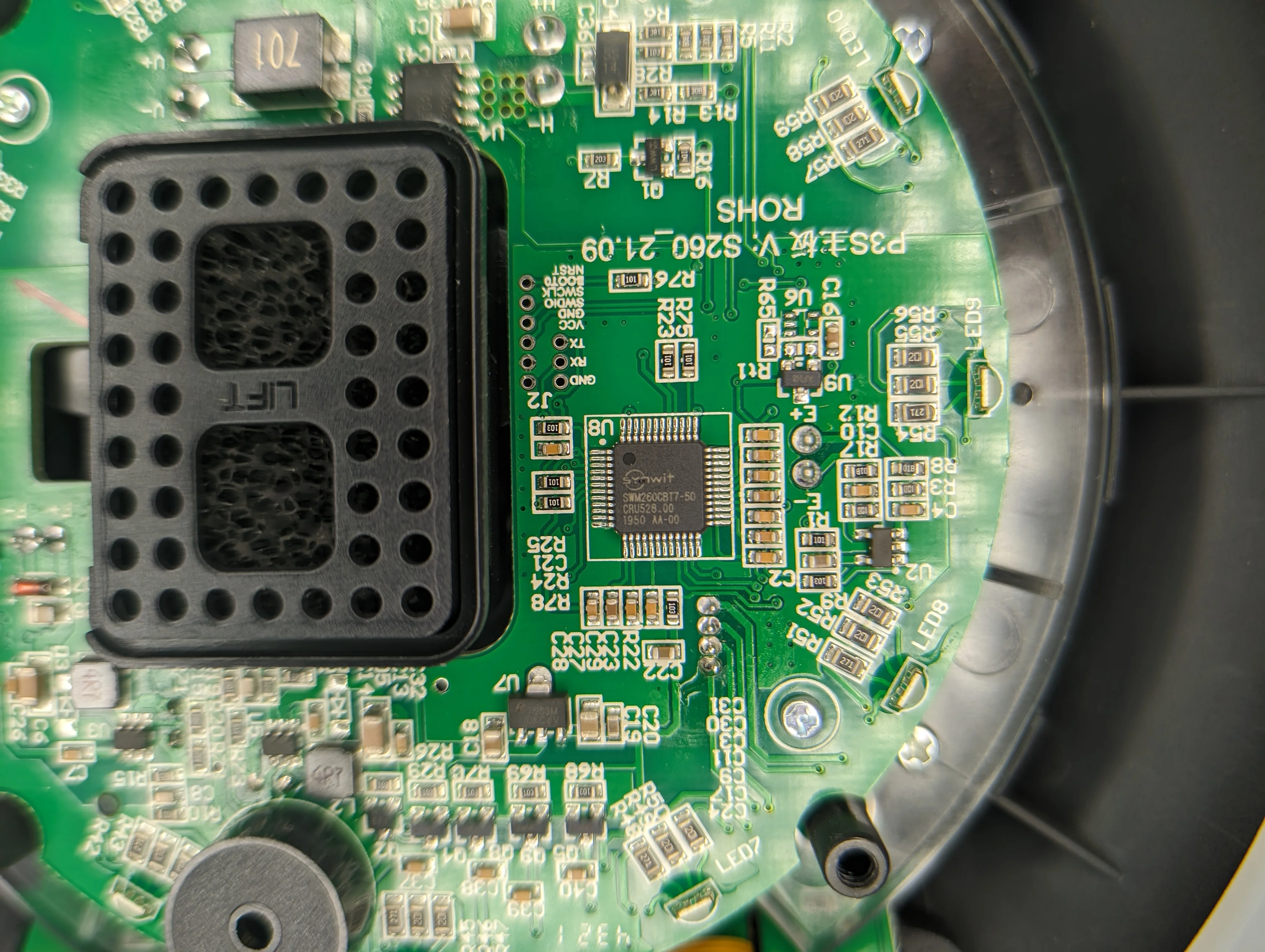
Close up of the main application processor.
Note that the DC jack is on a separate board that is easily removed. This is a nice touch as it makes it easy to replace if it ever breaks; it’s a standard 5.5mm OD barrel jack so sourcing a replacement should be easy.
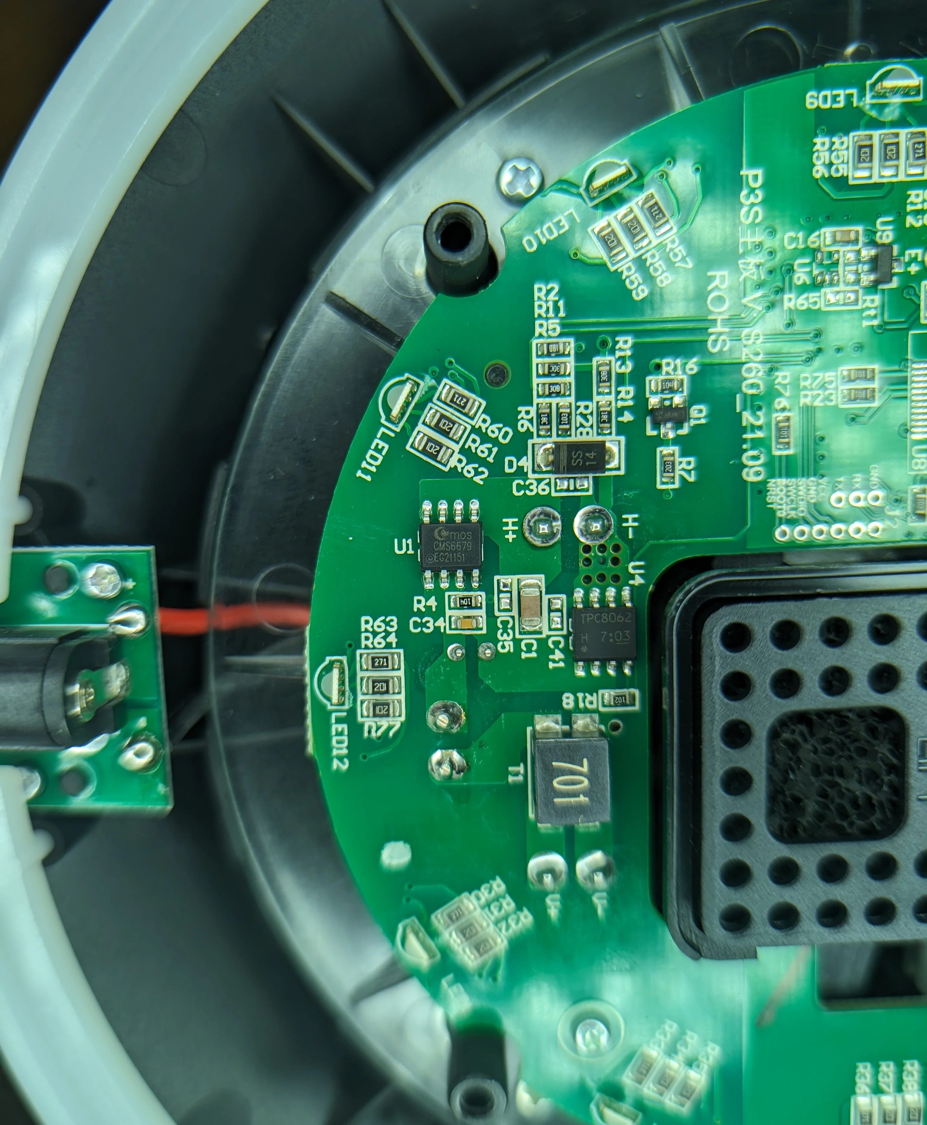
Close up of the two MOSFETs used to control the heating element.
The PCB is almost entirely single sided; only a few passives and connectors for the various peripherals are on the top side.
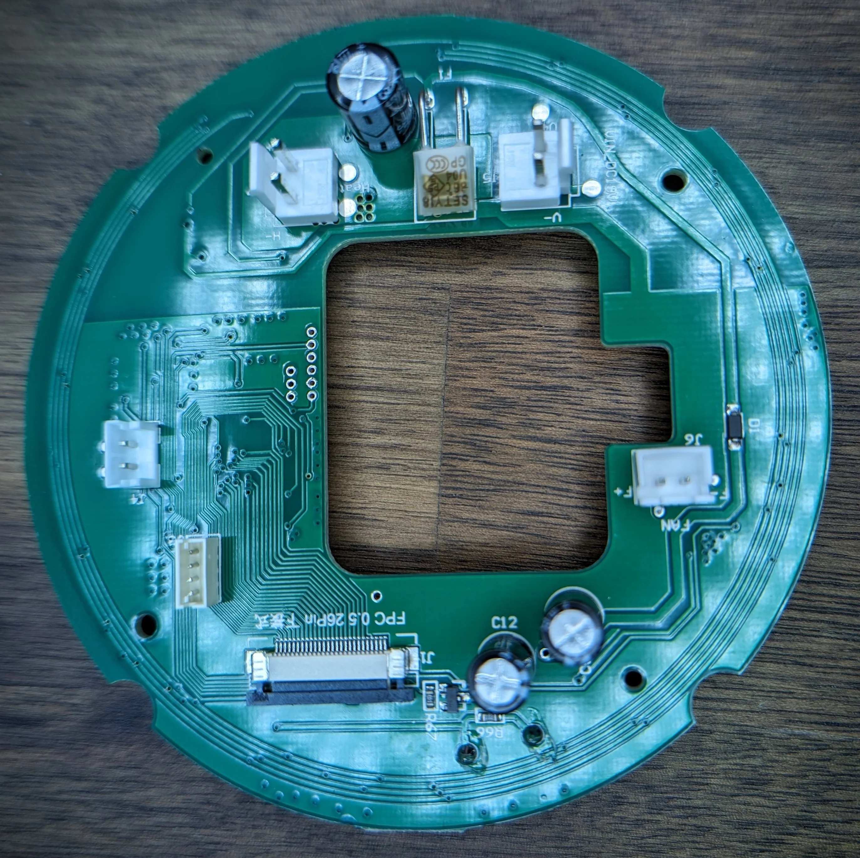
The top side of the main PCB. Sorry for the off-center angle and the glare.
The power supply isn’t exotic so sourcing a replacement should be easy if it ever fails. It’s also worth noting that the 19V / 3.42A rated output is really close to 20V / 3 A output profile from USB-C PD 1.0 spec and totally within the adjustable range of a USB-C PD 2.0+ power supply. It should be possible to adapt this device to use USB-C PD power with minimal effort if needed.
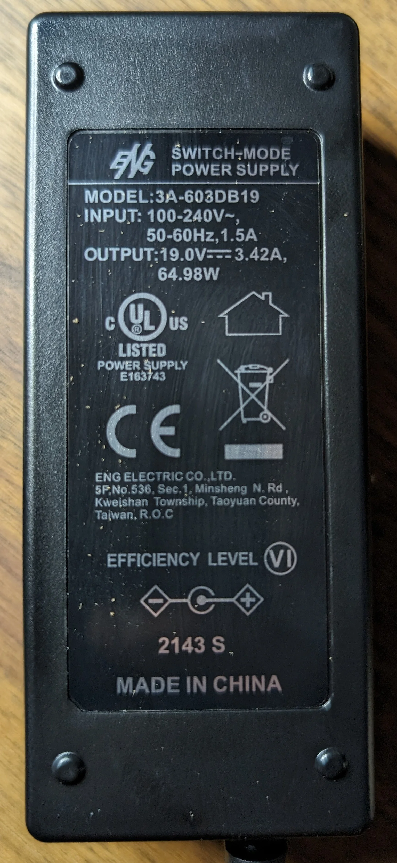
Power supply is pretty standard; feels well made.
All in all, I’m impressed with the build quality of the device!
It’s well made and easy to service. No glue or clips to break, no hidden screws to find, no proprietary connectors to deal with.
The main PCB is well laid out, all components are marked with crisp silkscreen and nobody lasered off the markings on the ICs.
The most dangerous part of the device it the heating element and there are multiple heat-shields between it and the user and all the heat-shields are easily replaceable!
The PCB designer also knew that MOSFETs can fail short so they use both a high and low side FET to control the heating element!
Normally little piezo beepers are annoying but this one can be attenuated or disabled in software.
I was pleasantly surprised to find that the device does have a UART and programming port onboard but I was not given permission to probe further.
My friend decided that IR control would be sufficient for their needs so I don’t have any more information about the UART.
Notable Chips and stuff
SWM260CBT7-50: This is the main application processor. The manufacturer’s product details page has both a (Chinese) datasheet and a collection of reference code.
Assuming the read/write protect fuses aren’t blown, it should be possible to dump the firmware from this chip and possibly come up with an open-source replacement firmware for the device. With the UART so nicely broken out, adding in an ESP32 or similar to provide wireless control should be trivial… :D.
CMOS CMS6679: MOSFET driver for the heating element.TPC8062: MOSFET driver for the heating element.
ESPHome IR Remote
I already mentioned this above but it’s worth repeating!
Basically, the code below emulates the IR remote control that comes with the device. As there is no way for the device to communicate back to the original remote to say “I got your command” or “I’m busy right now, try again later”, there’s no way to know if the device is in the state you think it is.
The human operator can see the device’s state and confirm that it’s doing what they want… but this is not the case for the ESPHome/Home Assistant integration.
The device also has a few safety features built in that the “remote” can’t bypass. If - somehow - the integration becomes fully broken, it’s no different from sitting on the remote or otherwise spamming some signal. In this case, the device will still operate safely.
If you understand the risks and still want to proceed, here’s a simple ESPHome configuration that will allow you to control the XQ2 via IR blaster.
| |