AliExpress 11.11 Sale Teardowns (2024 edition)
11-11 day teardowns (2024 edition)
I guess this is becoming a tradition now?
During China’s Single’s Day sale on AliExpress, I bought various gadgets - both for projects and out of curiosity. Rather than write separate posts, here’s a collection of mini teardowns showing what’s inside each item.
Previous years:
Tuya Zigbee 3.5 Inch Smart Wall Switch
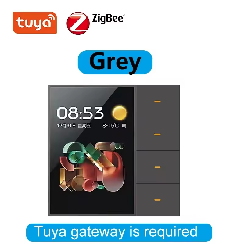
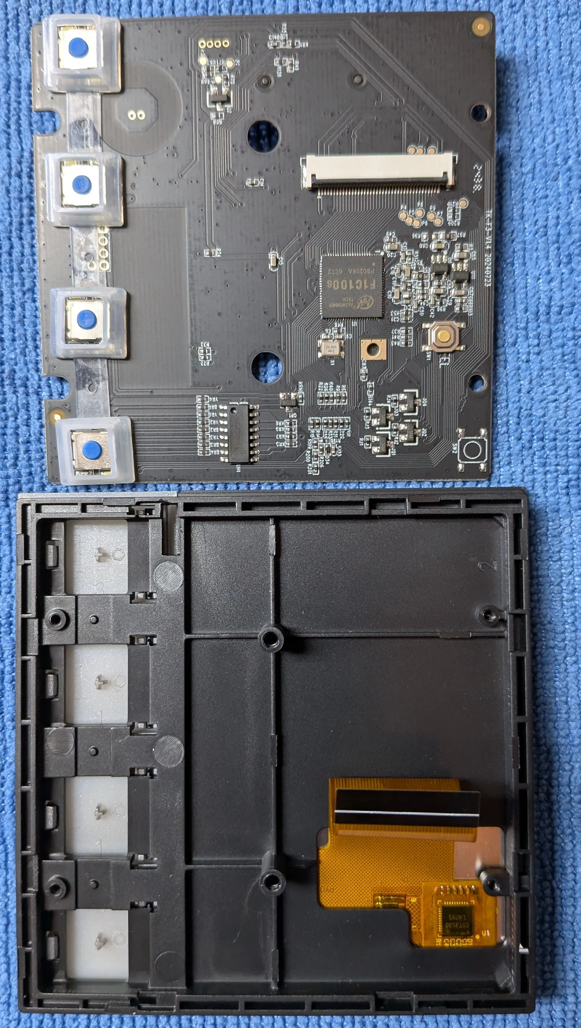
I’m always looking for a better scene controller/switch/Home Assistant interface. I was curious about which chip they used for the full graphics display and was hoping for an easily hackable Android device. Unfortunately, no such luck with this.
The main application processor is F1C100s which is a low-cost, low-power, ARM9-based SoC.
It might be able to run a custom Linux build that could draw a custom UI, but it’s not going to be as easy as rooting an Android device.
There’s not much in the box, just the switch and a manual.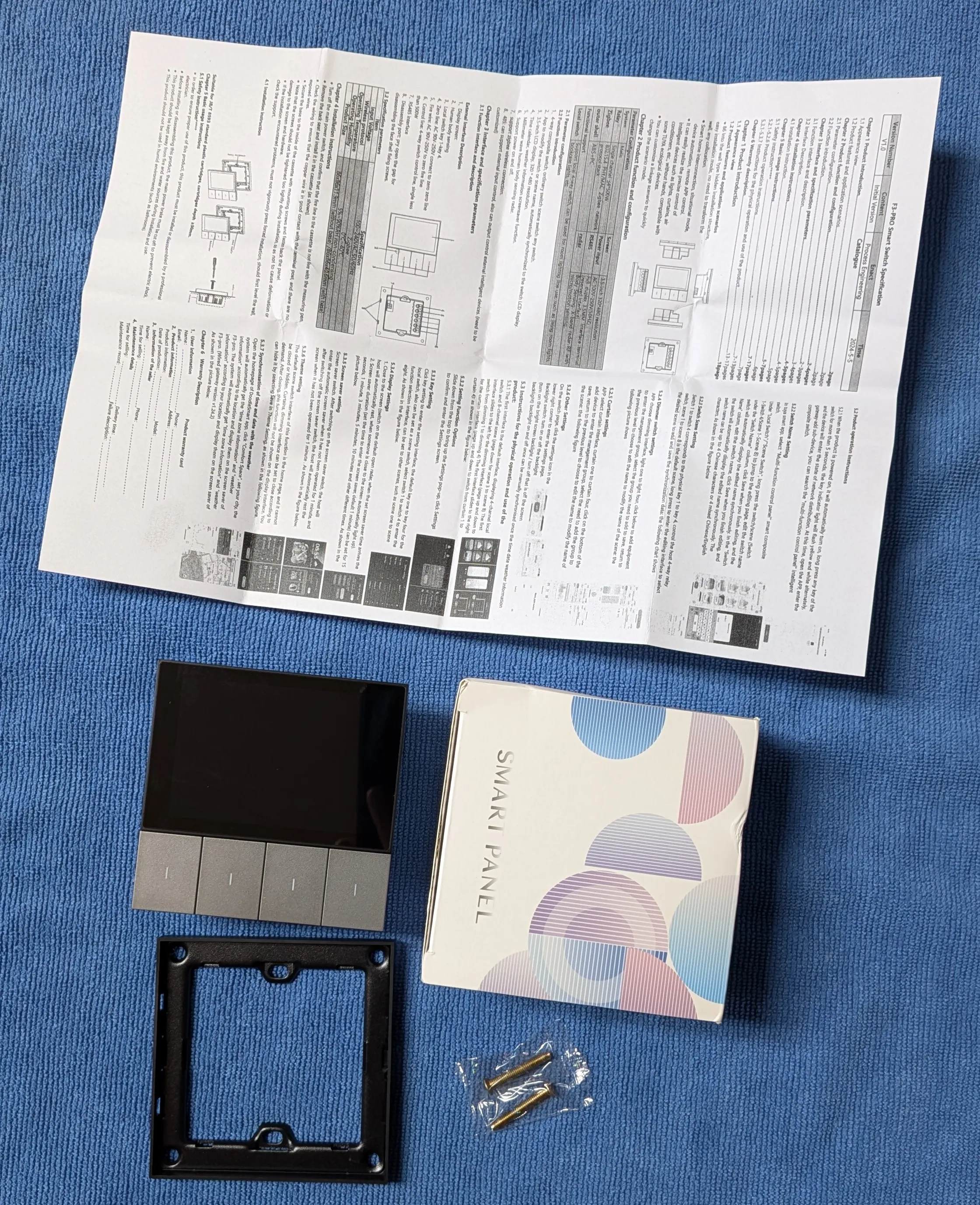
It’s a pretty standard “power supply and relays in the back, touch screen in the front” design. This time, though, there’s an exposed programming header!?
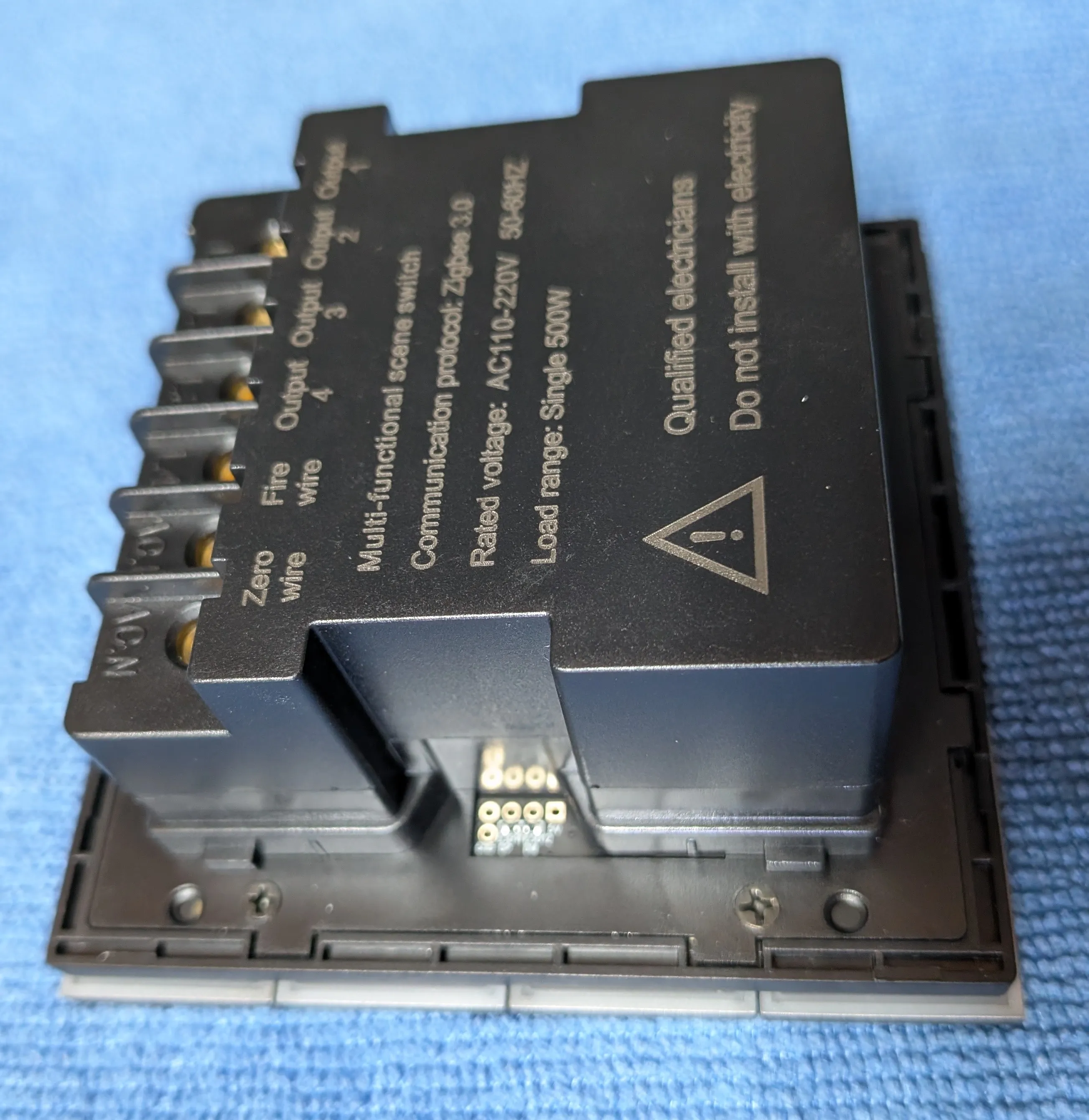
Note the 'fire wire' label for mains input... :D
A few screws later, the back panel comes off to reveal some power regulation/switching components and the Zigbee module.
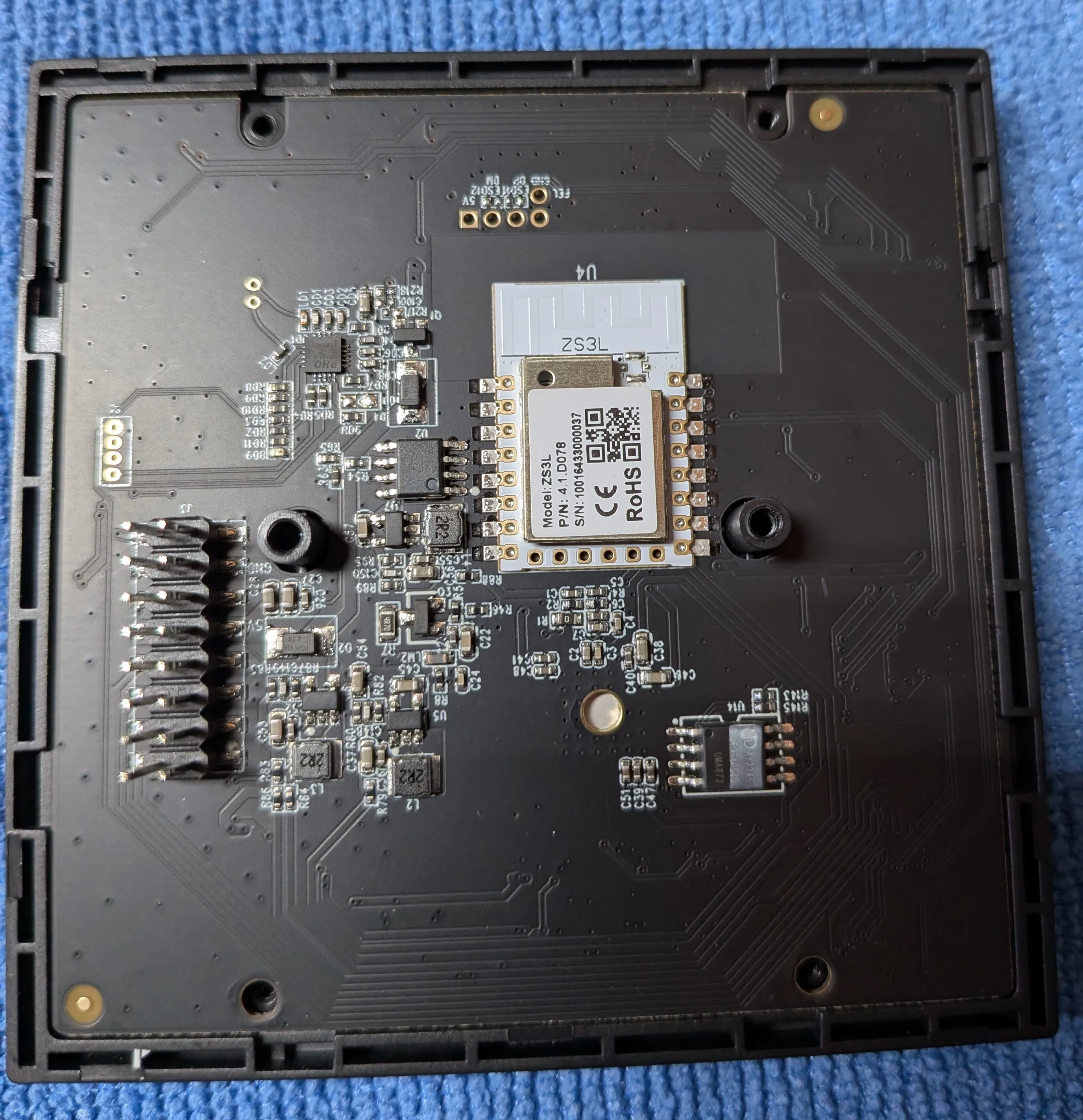
They achieved the “mushy, then clicky” feel of the buttons by using a rubber insert around the tactile switches.
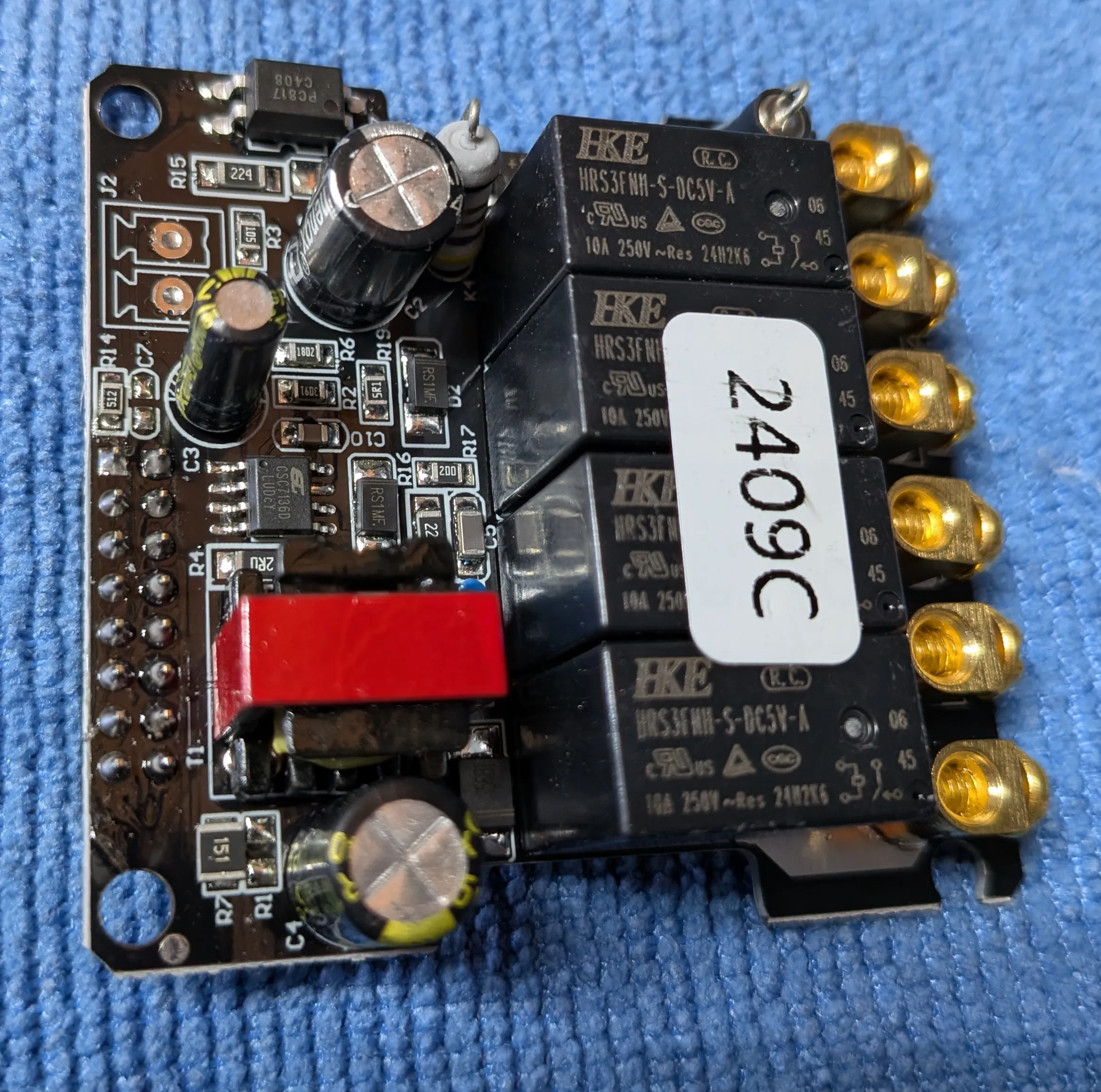
The power supply doesn’t look too bad. Clearance looks OK, there is a fuse, and the soldering is decent. I don’t know how well isolated that transformer is, but it’s probably fine.
J2 looks like it might be DC input or possibly RS485 for a future model?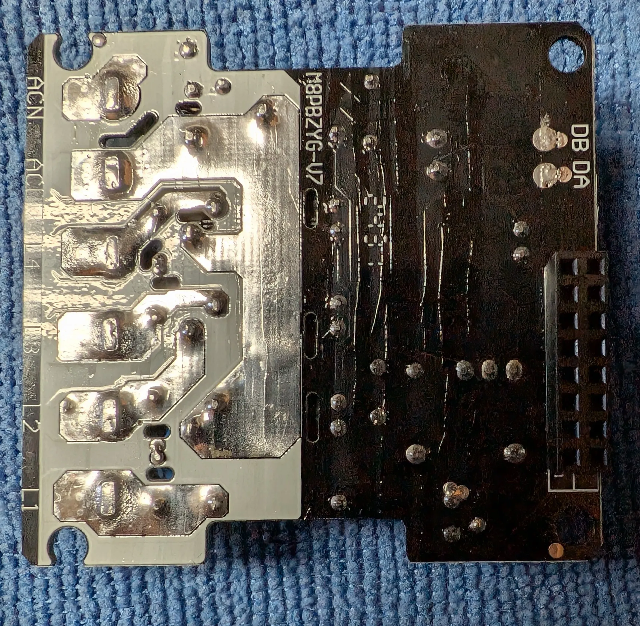
Ueetop 175W GaN USB C Charger (BK-112D)

As the USB-C PD standard matures and GaN technology makes high-power chargers cheaper, it’s fun to see the internals get more complex but also more integrated. This was less than $15 shipped which is insane for a 100W+ charger unless they cut corners somewhere…

Hey, it came with a mains cord and it's even correct for my country!
There are a LOTS of chips holding things together; it’s almost impossible to open this without breaking at least one! Consider this a warning: you will be doing a destructive teardown if you open this!

Look at those PCB traces going to the output. Easily 5mm wide!
As this is a #TwoMinuteTeardown, I’m not going to remove all the silastic glue on the power supply module nor will I check the ripple in the output.

Other than that, it’s about what you’d expect from a modern USB-C charger that isn’t hyper-compact; beefy looking AC-to-DC converter, a few big caps and then the USB-C PD controller.
Between each group of ports is a series of passives, some beefy looking power MOSFETs and a protocol negotiation IC.


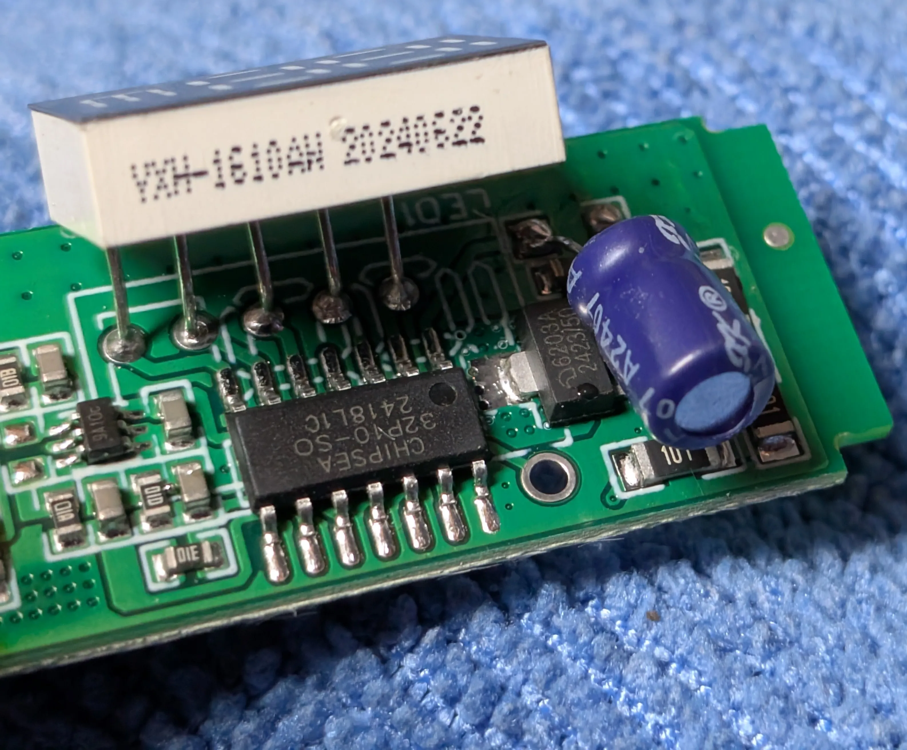
Notable ICs
Shenzhen Fuman Elec XPD977D30A
Generic Ozone generator (XD001)

There’s not much in the box other than the generator and a manual.

It’s easy to take apart with no hidden screws!

Inside, you’ll find about what you’d expect: a potted HV module, fan, controller, and a battery.

Instead of the cheaper “carbon needle” ozone generators, this one uses a ceramic plate.

Such a pretty glow!

Micro USB is INEXCUSABLE in 2024!
Annoyingly, they used a micro USB port for charging. This is inexcusable in 2024. The silk screen on the PCB indicates that the design is from late 2020, which would be slightly more acceptable if USB-C wasn’t already the standard by then. Furthermore, this device doesn’t need any complicated USB-C PD features, so it’s not like they’d have to worry about the extra cost or complexity of a USB-C controller. Really, all they needed was two (very important, NOT ONE) 5.1k resistors and a USB-C port and they could have been future proofed!

They scrubbed the markings off the SOIC16 CPU. The rest of the components are about what you’d expect for managing lithium batteries, switching the fan, and driving the boost converter for the ozone generator.
It appears another version of this device also features a buzzer. I’m not sure what for, but the silk screen clearly shows a spot for it.

BTF Light SP530E LED Controller

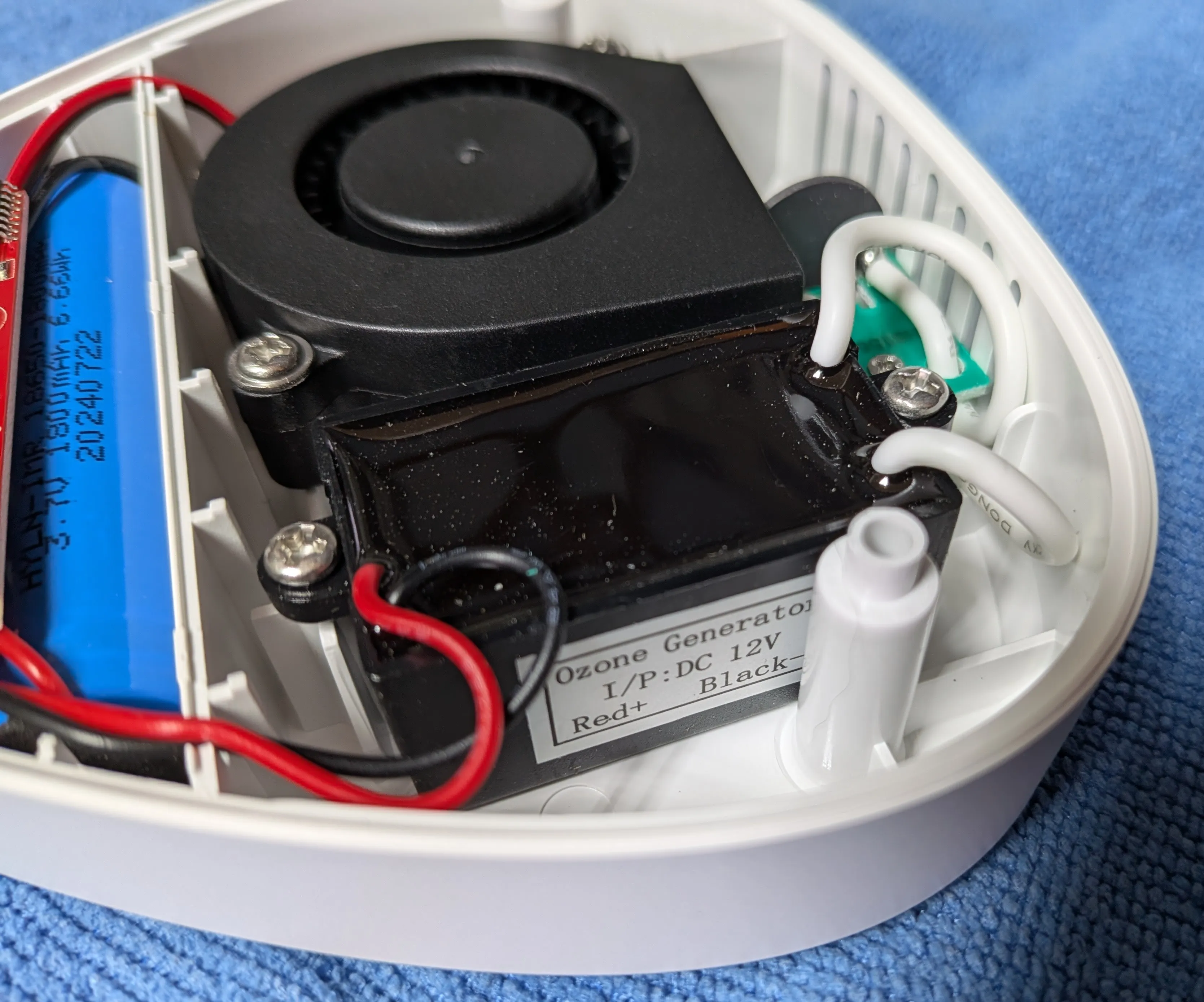
This is the first of a few LED controllers I bought to see if they are compatible with WLED or ESPHome. I have some thoughts on the state of the LED controller market, but to summarize: it’s getting better!
The packaging is very nondescript, containing just the controller and a manual.


They did include a screwdriver, which… makes me wonder how many people are buying the individual components to DIY a LED lighting solution but also don’t already have a screwdriver?

The PCB is pretty simple and, thankfully, is nothing more than an ESP32 and a level shifter. It also includes a small condenser microphone for the music reactive mode.

The MOSFETs look robust enough to handle a decent amount of current, and there’s a decent amount of via stitching around the power traces, so it should be able to handle the heat.


They labeled the programming header. ❤️
Notable ICs
TM(Shenzhen Titan Micro Elec) TM74HC245
Gledepto GL-C-015WL-D LED Controller

As with the other device, this controller also has bare-bones packaging.
No screwdriver needed because all the terminals have their own locking lever!

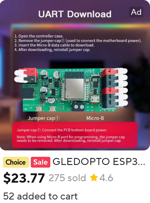
Happy to see an ESP32 module in here… on its own PCB? Complete with a micro USB port for flashing?!?

Yep, the ESP32 is on a separate PCB that’s connected to the main board via a header. The silk screen on the PCB makes me think that this was initially developed for an ESP8266 but then they added the header for the ESP32 module late(?) in design.

The silk screen is really well done; everything is labeled well.

Really happy to see that the GPIOs are labeled... for both the ESP32 and 8266 variant!
Because this is an “addressable” LED controller, there’s not much to look at. The GPIO from the ESP goes more or less directly to the output pins.

And in case there was any doubt, the back of the PCB makes it super clear that this PCB can be used with an ESP8266 or ESP32.

SMLight A1-SLWF-03 LED Controller

I saved the best for last! This LED controller really did surprise me with how open it is!
They’re not putting a generic “ESP32 powered” message on the label leaving the reader to read between the lines / infer that the device can be flashed with alternate firmware.
They’re straight up saying so! The label has the GPIO pins clearly labeled. It uses USB-C for power and flashing. The USB port is modern unlike other devices I’ve shown in this post. The USB port can also be used for programming and isn’t hidden!
Here’s to hoping that they release a version for analog LED strips! 🤞
🇺🇦


side note: the OSS/HA community is being heard
Over the past few years, I’ve been scouring AliExpress to find the latest and greatest in LED controllers and every year I’ve been disappointed. But over the last year or so, I’ve noticed a huge uptick in the number of controllers that are actually compatible with Home Assistant and other open-source home automation systems.
In the beginning, they were all ESP8266 based and trivial to reverse engineer and flash. Then they started using TuYa intermediate MCUs which were a bit more tedious to reverse engineer but still possible if you were willing to put in the effort.
Now, they’re using ESP32 based chips and going out of their way to LABEL which GPIOs go to which pin(s) and to generally make it TRIVIAL to flash WLED or ESPHome or whatever you want.
This means some savvy manufacturers are paying attention and recognizing the growing hobbyist market for these devices and are catering to them. There’s somebody out there that’s not going to force their garbage app/api on you and is going to let you do whatever you want with the device you bought. This was UNHEARD OF just a few years ago and I’m so happy to see it happening now!
This is such a victory for the DIY/HA/OSS community!
G3061 PD65W Mini Hot Plate

And the winner of the “feels most like a hand-built prototype” award goes to… this thing!
Normally I don’t like it when screws are hidden under labels / stickers… but in this case, the “sticker” is a rubber foot that doesn’t even “hide” the screws.

Those lumps under the rubber mat are the screws holding the case together.
Looking from the side, the construction becomes pretty clear; it’s probably just using a PCB for the heating element and the stacked PCBs separated with little brass standoffs is for thermal isolation.

USB-C for power is always a good sign. Other than that, a basic CMSemicon IC runs the show.
The OLED screen module is for sure one of those prototype modules meant for hobbyists!

The use of threaded inserts for nuts just screams 'prototype' to me. Nothing wrong with that, just makes me smile.
As expected, the heating element is just PCB traces on an aluminum substrate PCB. Cheap and effective!

If anybody needs the instructions for this, I scanned a copy and you can get it from here.
Generic USB-C Dock w/ LCD

USB-C “expansion” docs are a dime a dozen now. This caught my attention because of the LCD display on the side. What are the odds that it presents as a second display using display port tunneling via usb-alt mode?
There are no screws, just clips.


It looks like a pretty straightforward de-mux and breakout PCB. The display is an isolated / standalone component that’s linked to the main PCB with just 4 wires. What are the odds that it’s hanging off a USB hub?

I'm not exactly sure why they made the USB-C "tail" detachable.
The silk screen markings make me think that the “internal” name for this product is K0108-1D.
Interesting that the HUB PCB has a date code almost a full year after the LCD PCB..
Also worth noting; the instructions that came with the device link to the same shady key123.vip site that the ajazz used so there’s definitely some sort of relationship between the two but I’m not sure what it is.


Annoyingly, they lasered off the markings on the display module. I don’t have a clip for the eeprom, but I bet that there’d be at least a few interesting strings in there :D.
I wonder what SW1 is used for... Nothing much on the under side of the USB-Dock PCB.

USB details
After seeing that the LCD is just a standalone module, I wanted to see how it presented itself to the host. As expected, it’s just a USB hub with a few devices hanging off it. The display module is almost certainly the HID device.
| |
And here’s dmesg with the screen not attached versus attached:
| |
And with the screen attached, there’s some additional lines as another device is enumerated:
| |
Ajazz AKP03E (Stream Deck clone)

This is a clone/knockoff of the Elgato Stream Deck products. I was curious to see if they did anything differently than the original for the internal hardware. Turns out, no. It’s still a basic LCD screen behind a matrix of clear buttons.
The unit can be easily separated from its stand and there are no hidden screws!


After going around the edge w/ a spudger, the internals reveal themselves.

The -VxNx suffix on the silk screen matches the silk screen seen on the USB-C Dock… which really does make me think that there’s some sort of relationship between the two products.
The board with the physical knobs/buttons is just a “pass through” PCB; everything here just goes right over the FFC to the board with the screen and buttons.

I can’t find anything when googling the main IC, unfortunately.
ARX29025
Q2402
The silk screen is:
HSV293-N3-LCD-V2P1
20240620


The software is super sketchy; just trying to find a build that actually worked on macOS was a pain!
The official site looks and functions like it was made with a 2000s-era website builder 🤮.
With some google-fu, I found links to a web forum that may not be officially related to the product, but has some download links to software that is supposed to work with the device, on macOS in English.
I never got a working build of the software, but the few builds that I did try all have the same architecture; a Qt app that hosts plugins and does all of the thinking for the device.
With a bit more digging, I think that this “Mirabox” company is the underlying OEM and the ajazz is just a white-labeled version of this product: Stream Dock MBox 293N3.
Mirabox also appears to have a fledgling SDK for plugins and a Python SDK for Linux users!
USB details
Similar architecture; USB hub with two HID devices hanging off it; probably one HID for reading the buttons and another for writing to the screen.
| |
And dmesg:
| |
Generic WiFI LED Wall Clock

I’ve been looking for a “Works with Home Assistant” version of the Echo Wall Clock ever since Amazon discontinued it.
I was hoping this would be a simple ESP8266 or ESP32 module linked directly to the LEDs… but there’s an anonymous intermediate microcontroller in there.
Assuming that the microcontroller can be removed easily and the various segments of addressable LEDs can be driven directly from an ESP8266 or ESP32, this could still be a viable base for a custom LED wall clock.
Why bother with a custom USB cable? Just use a standard USB-C jack for power! Lots of SMD neopixels and a partition/mask system to keep high contrast between the segments.


Kinda interesting to see how they spread the components out to not interfere with the partitions.


PCB marking: YC-9108-WIFI-0807, Ver 1.6, 2024-6-8

Markings have been sanded off. Why bother? What's the value in that?

I assume this is i2c for the RTC module.
Mirabox N4
This was actually a late addition to the list. Technically I didn’t order it in 2024, but after learning about the Ajazz possibly being a Mirabox product, I wanted to see if there was anything interesting in the Mirabox product line so I found this for a reasonable price and held off publishing this post until it arrived.

The packaging is nondescript and minimal; the unit and a nice USB A -> C cable is essentially all that’s in the box.

Did they have to use foam for this? Cardboard would have been fine...

The Mirabox logo on top is laser engraved which is a nice touch.

No screws, just clips! And they're not even that hard to find or pry up!


As was the case with the other LCD modules, this looks like it’s just USB 2.0 module hanging off a USB hub. Conceivably, you could embed a tiny raspberry pi zero or other small computer with USB Host support inside this thing 🤔…

Really nice ofd them to label each FPC connector.

The two internal PCBs are marked very similarly to the USB-Dock and the Stream Deck clone which really does make me think that mirabox is the ODM for those products as well.
Markings:
HSV293-N4-LCD
20240807
HSV293-N4-SW
202400711
And the USB hub PCB in the base doesn’t have a part number, just a date code. I’d bet that they started designing this product in spring of 2024 and they finished the simplest part - the USB hub - first.

As expected, the buttons and the lower display are really just different regions of the same LCD.
The dials are aluminum, which feels very premium for a device that’s otherwise plastic.
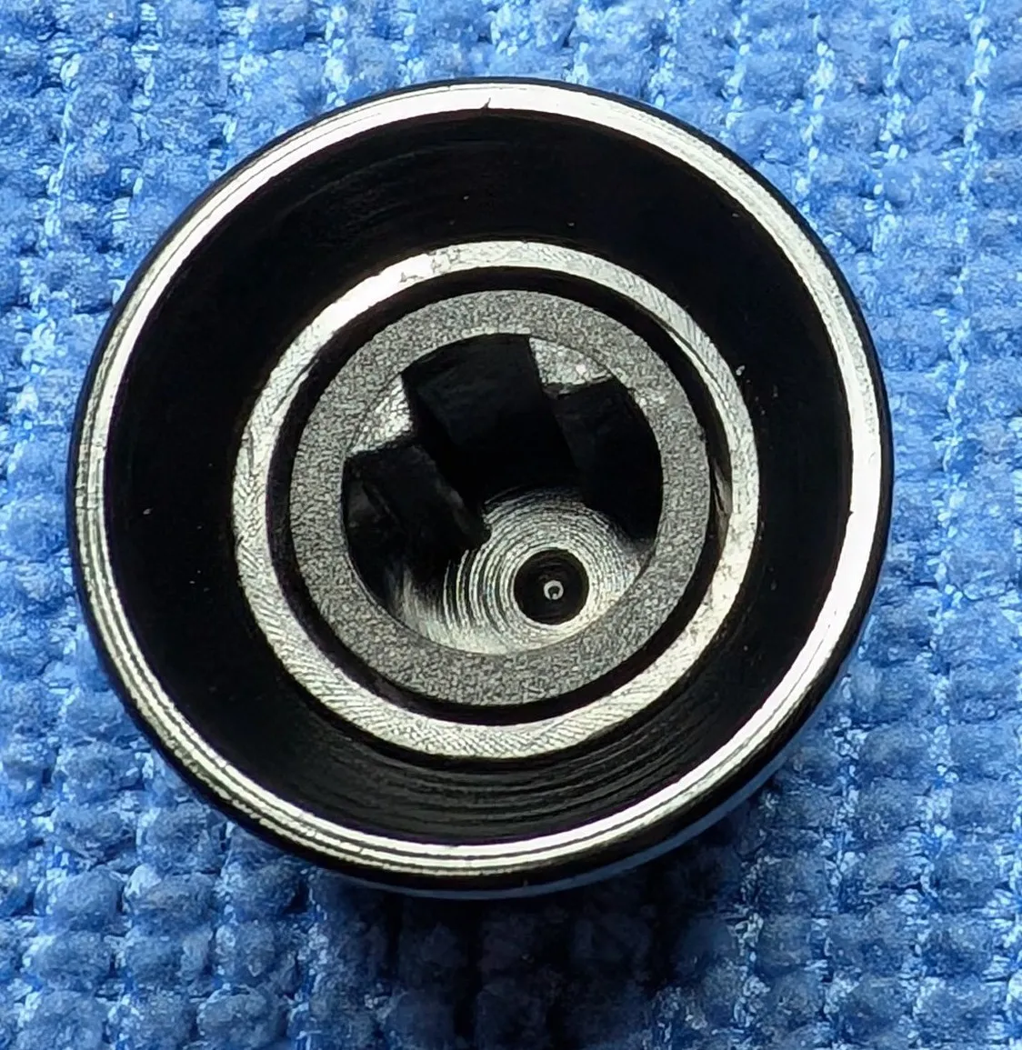
That plastic insert almost looks 3d printed...
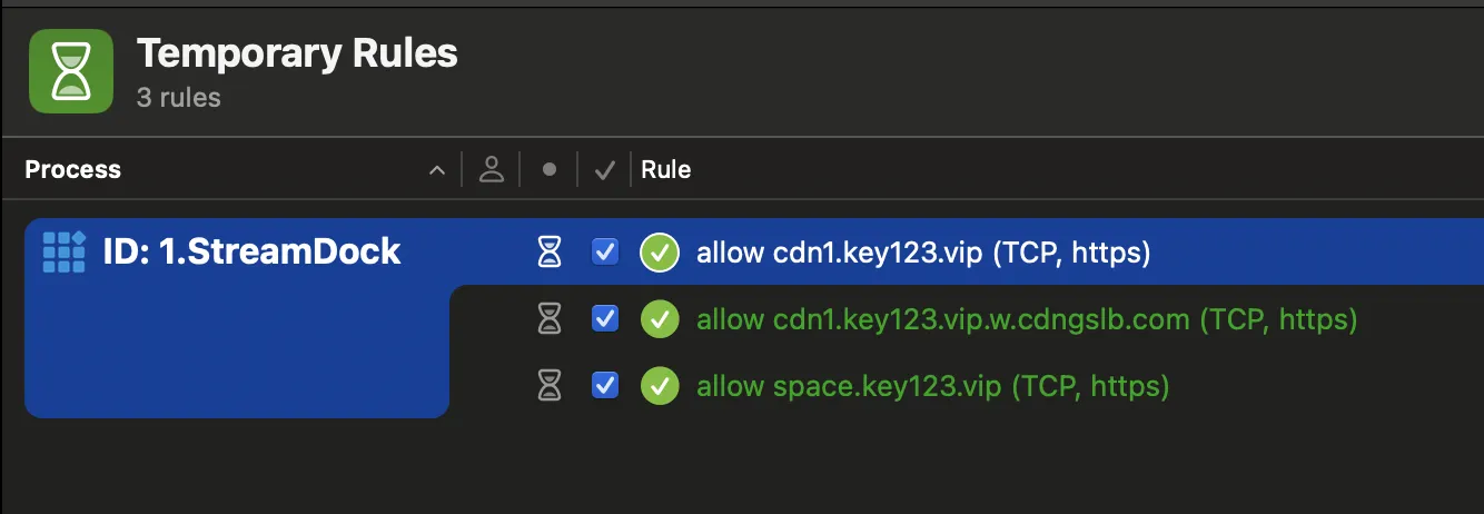
Interesting to see what network calls were made...