I made a thing: Yet another 3d printed speaker
Background
Long story made very short: the amplifier inside my ancient 2.1 desktop speakers died and I couldn’t find anything “off the shelf” that would serve as a suitable replacement and integrate well with Home Assistant.
So if you can’t buy it, you have to build it! And as it turns out, there’s a whole community of audiophiles that have published designs on all the usual places you’d find free designs for makers. Similarly, there’s a few companies that seems to specialize in audio electronics aimed specifically at people that are building their own speaker systems and just want someone else to handle the electronics and software.
This post will cover the design tweaks I made to an existing subwoofer assembly and an original amplifier electronics/enclosure design.
The components
There are two assemblies in this build: the subwoofer and the receiver/power-electronics enclosure.
The subwoofer is a remix of the amazing Skeleton Waveguide Subwoofer Speaker by zx82net which is a remix of "HexiBox" Tang Band W3-1876S Subwoofer Enclosure
by hexibase.
As for the drive electronics, I elected to use an Up2Stream Amp 2.1 - Multiroom Wireless 2.1 Amplifier Board.
This appears to be based on a MediaTek based module module from LinkPlay.
I could do a whole series of posts based on the firmware alone but for now I’ll just say that it is 1) trivial to root and 2) should not be exposed directly to the internet for any reason whatsoever.
I’m not equipped to verify any of the claims made by the original subwoofer designer so I can only offer my subjective take; this subwoofer offers more wubz at greater distances and that’s before I add +10db to the bass via the equalizer on the amp!
Tweaks
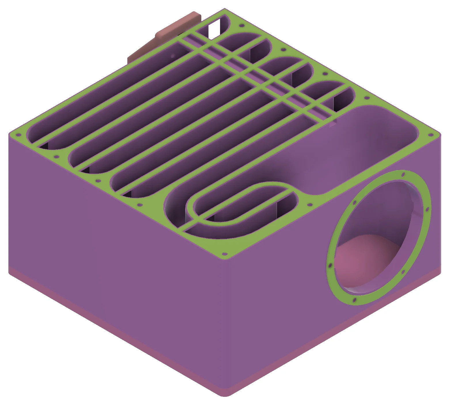
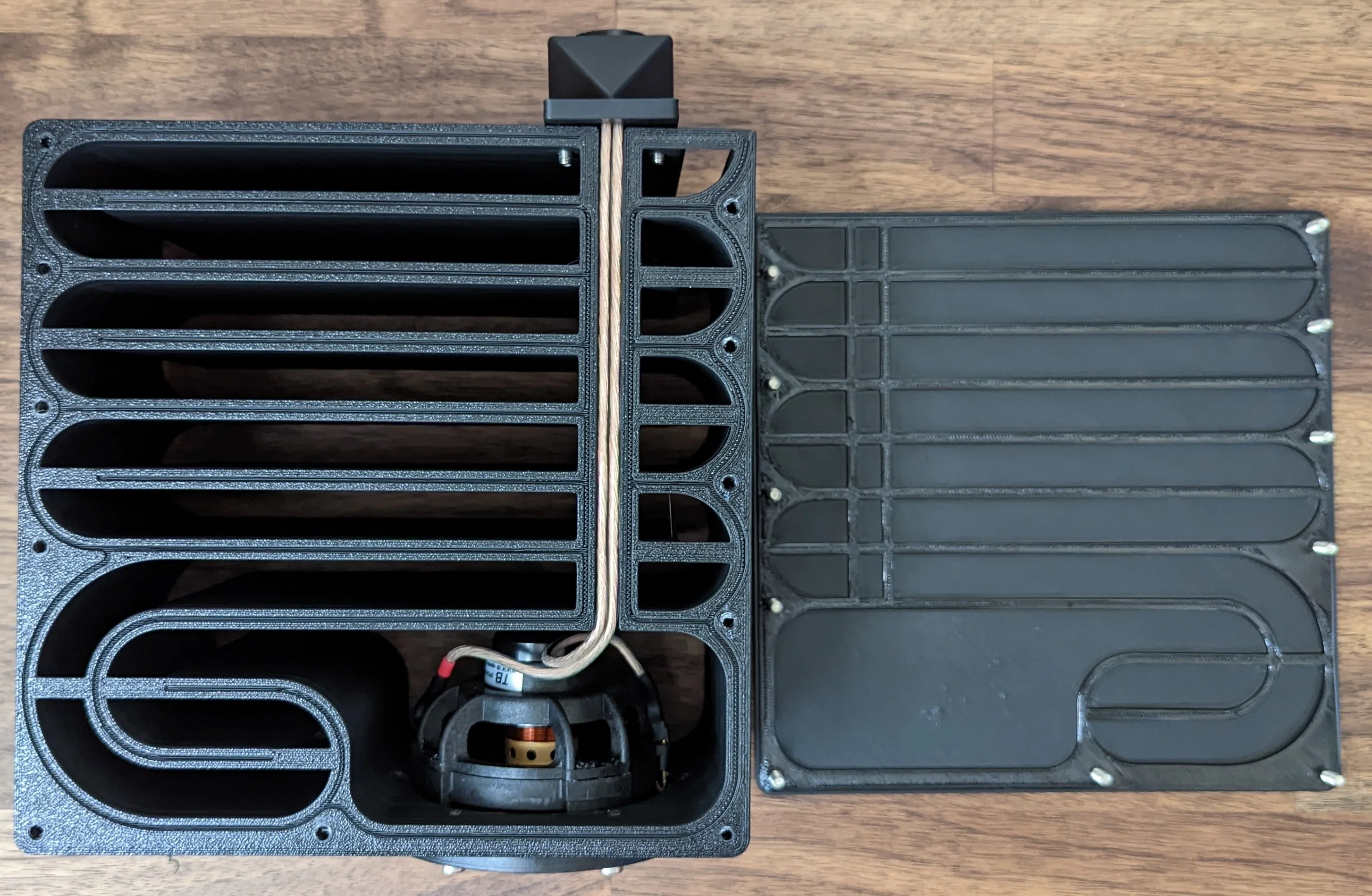
The green elements are meant to be printed in TPU or another gasket like material. The cable channel runs from the RCA jack enclosure in the rear (pink color), under the gasket material to the main speaker cavity.
Wiring
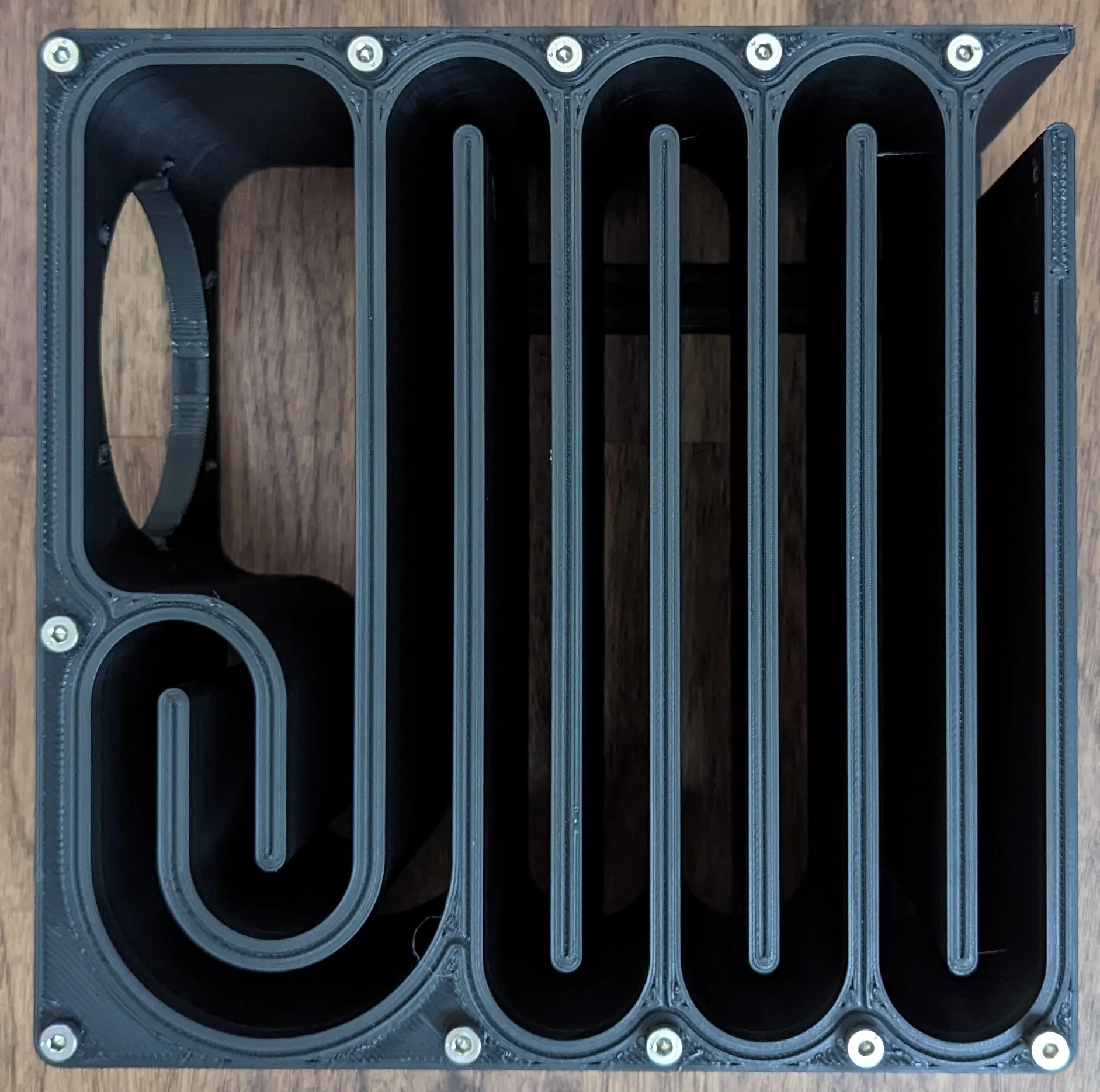
- There is now an integrated channel for standard 16 AWG speaker wire that runs from the main cavity, through each baffle, to the exterior.
- This cable channel also increases rigidity which aids in printing and assembly.
- The rear of the subwoofer body features some attachment points for a simple enclosure for speaker hookups.
- I am using RCA jacks but the enclosure could be easily modified to work with any similar connector.
- The enclosure mounts directly over the cable channel so all wires are protected/hidden.
Assembly
You no longer need to use goopy adhesives to seal the panels to the body! The sub body and panels have been modified to accommodate a thin 3d printed sheet of TPU or similar material to act as a gasket.
There is also a subtle channel cut into the sub body which is meant for gasket cord as a fall back.
The dark blue represents the path that gasket cord material should be laid down. When properly joined, there will be a slight interference between the panel and the gasket material; this ensures a fantastic seal.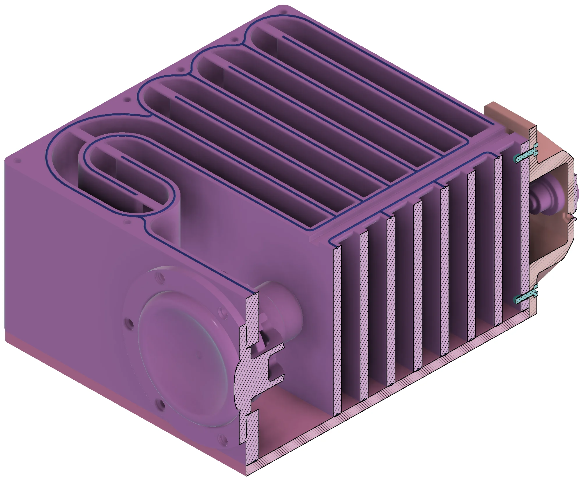

Mounting
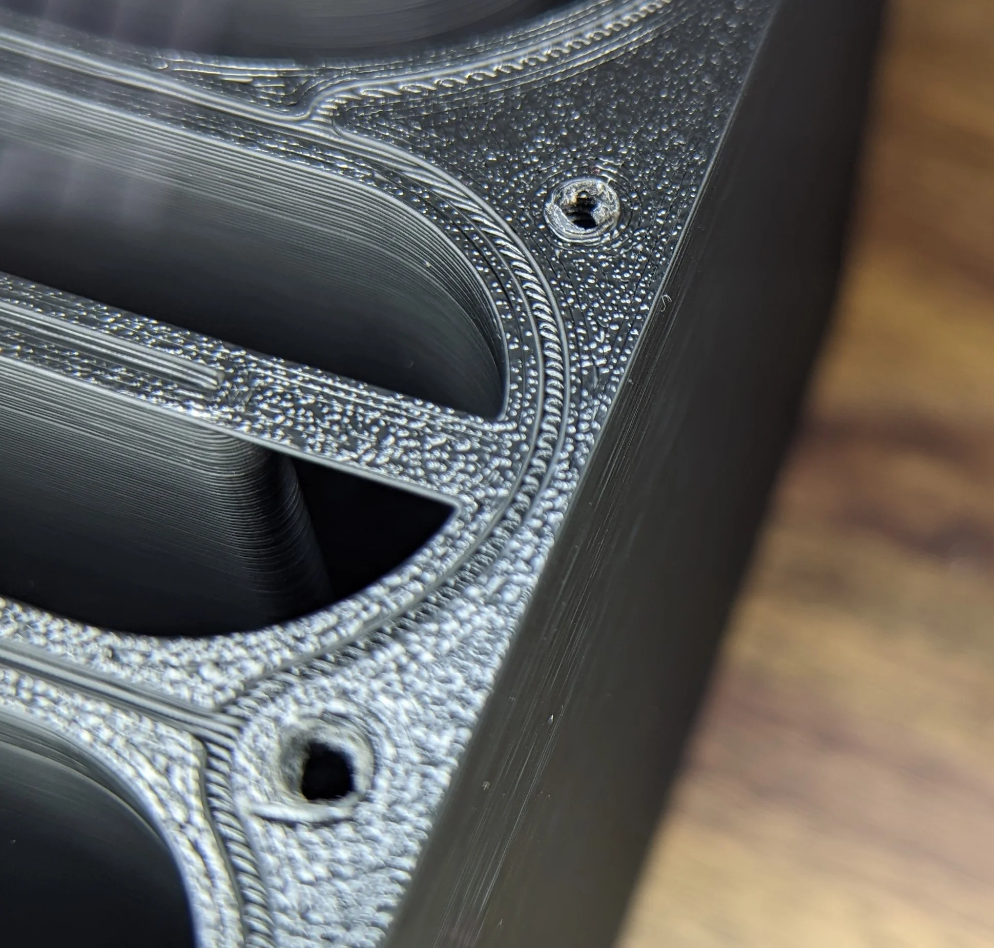
- The sides of the subwoofer feature a 100x100mm VESA/FDMI mounting pattern.
- When printing with the holes facing the print bed, support material all but entirely obscures their existence.
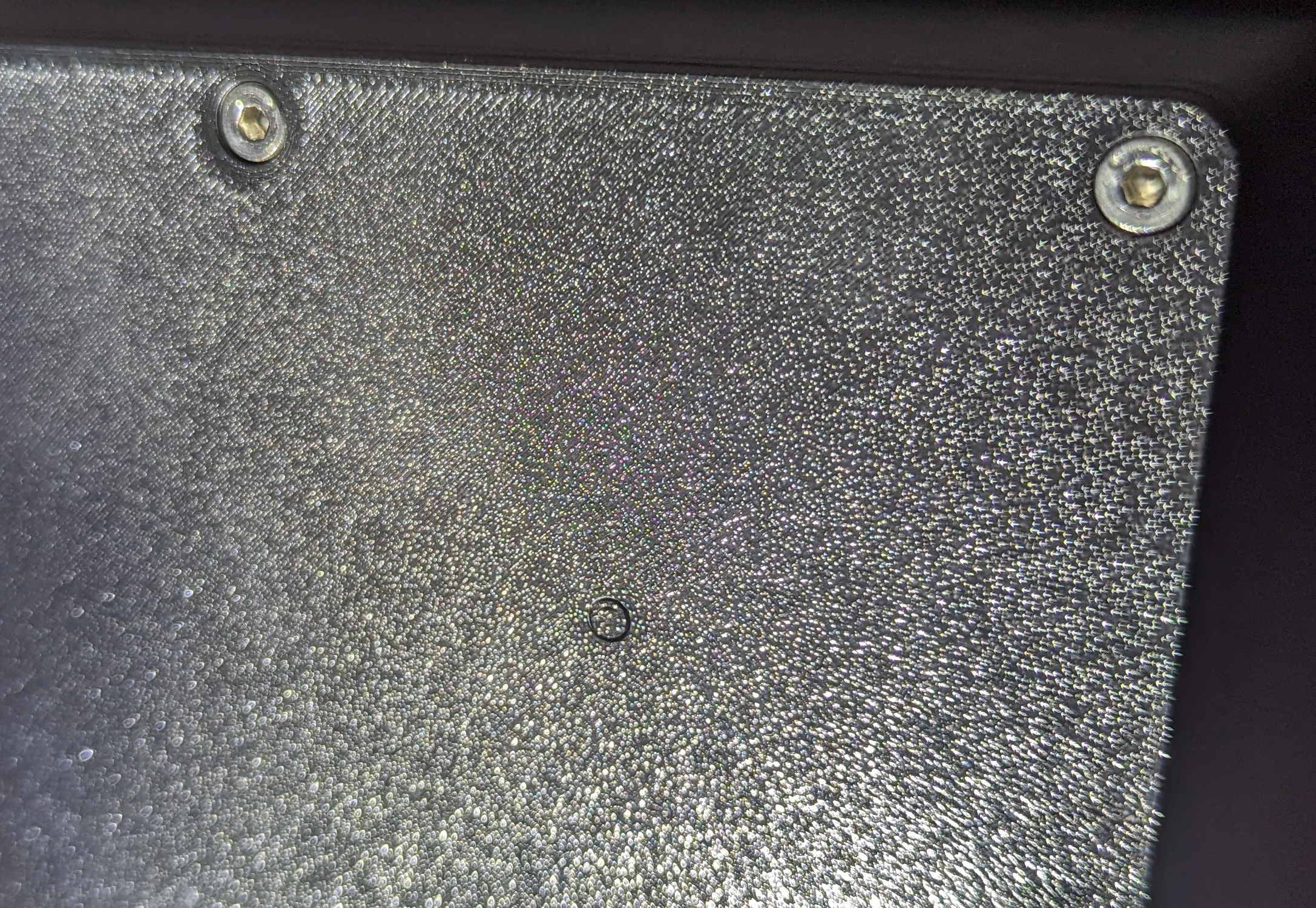
The support material hides the hole almost perfectly. If the image brightness wasn't turned up, you'd never notice :D
Build
BOM
Subwoofer
Very little about the subwoofer BOM has changed from the original design.
Optional: (1 mm) Buna-N O-Ring Cord Stock, 70A Durometer
- You will not need this if you’re printing TPU gaskets or using some glue / caulk.
- You will want some superglue or similar to help secure the gasket cord as you insert it into the channels.
16-Gauge Speaker Wire Cable, ~18 inches/40 cm.
- The cable channel was specifically designed for 16 AWG speaker wire with the dimensions 6mm x 3mm. Any wire can work but if there’s a gap between the wire jacket and the channel walls, you’ll need to fill the gap / seal the channel.
- 18 inches will allow for some relative comfort during assembly. You can get away with less but it will make some things a bit harder than needed.
28+
M4x 12mmscrews.- The original design didn’t include any specific screws so I explicitly chose McMaster # 90666A115.
- You will need at least 6 screws to secure the speaker to the sub and 11 to properly secure each panel to the subwoofer body.
- If you choose to install the electronics enclosure at the rear of the sub, an additional 4 screws will be needed.
RCA jack: there many different types out there but the parts are meant to be used with these jacks.
Amplifier enclosure
- The heart of the build is the Up2stream Amp 2.1 module.
- The AliExpress listing has a few versions. I was not planning on using the IR remote and I didn’t want an external PSU so I chose to order just the board.
Power Supply:
- The amplifier enclosure has room for a 24V 4.5A MeanWell LRS-100
- To connect the DC output of the LRS-100, you’ll need a female 3.96MM 2 pin connector to mate with the DC in on the amplifier.
Panel mount connectors:
RCA jacks: I used the same part number from above, just ordered a few different colors for the R/L/S channels.
Powercon True. Rather than a traditional IEC style or simple DC barrel jack + external PSU, I opted for a Skookum power connector. Like with the RCA jacks, there are many different parts from several manufacturers that will probably work but I specifically used this set from Ali Express.
RJ45: There are likely several that will work, but I explicitly used this part from Ali Express.
USB2.0: There are likely several that will work, but I explicitly used this part from Ali Express.
USB extension cable: You can find all sorts of adapters in every conceivable orientation on Ali Express from stores like this. For this particular project, you will need a 15 cm flat flex cable (
FFC) and 2x of the “straight” USB male connectors.
Screws:
The amp enclosure uses 4x of the same McMaster #90666A115 for external mounting but any M4 screw could work here.
6x
M3x8mmscrews to hold the amplifier PCB to the internal midplate and PSU to the case. Specifically McMaster #91290A113.4x
M4x50screws to secure the lid. Specifically McMaster #91292A140.
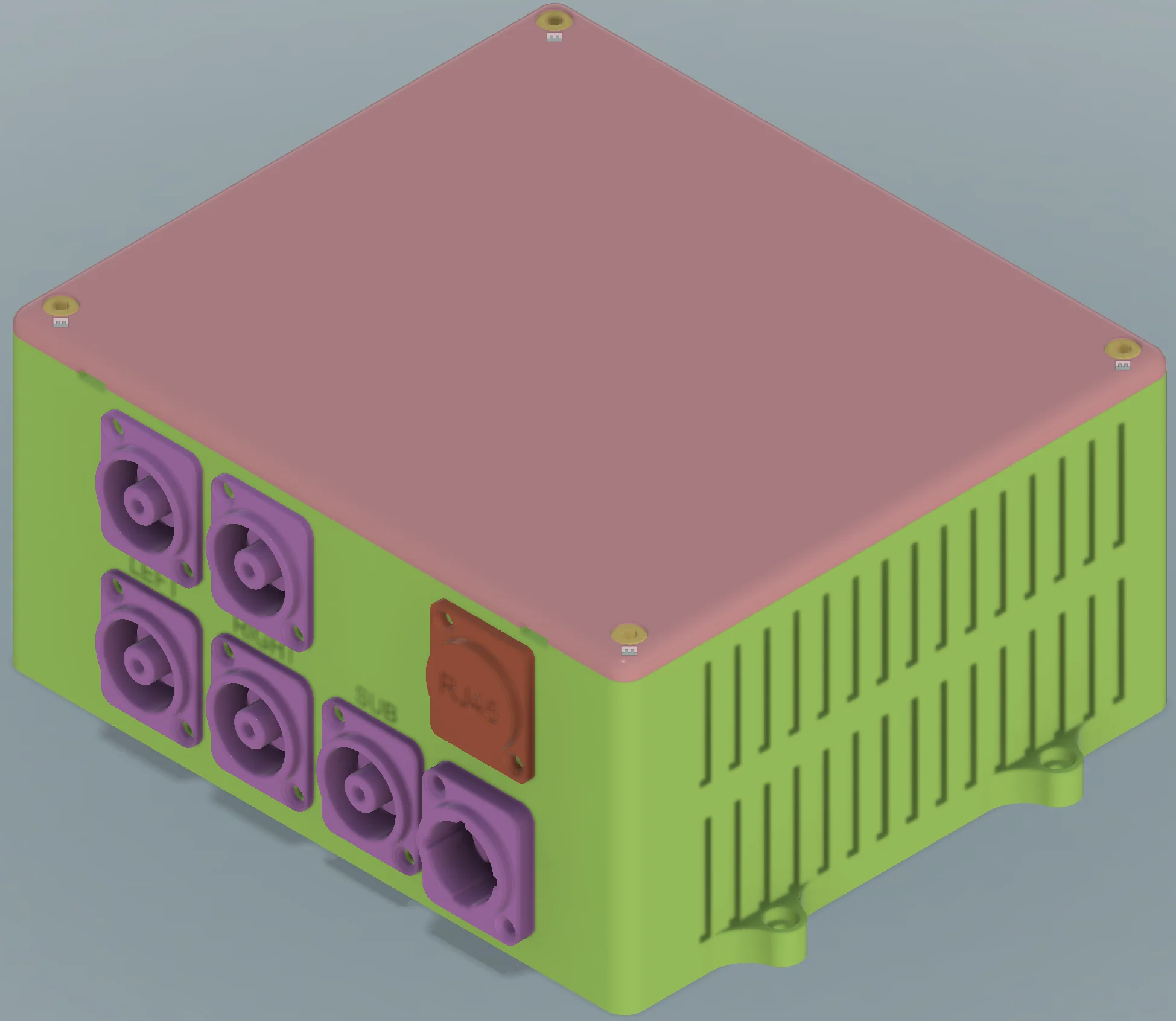
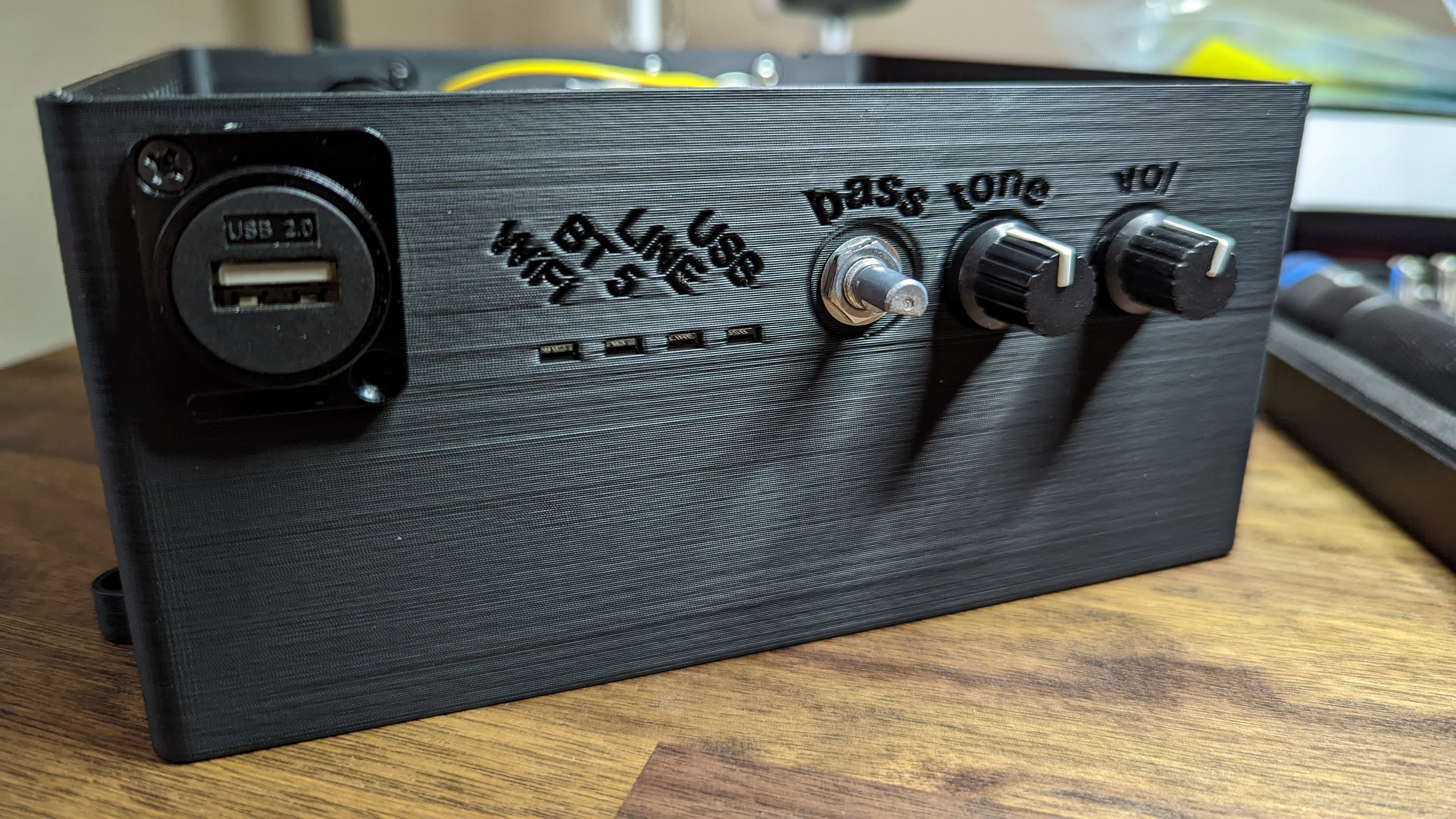
And it all fits together inside an enclosure like so:
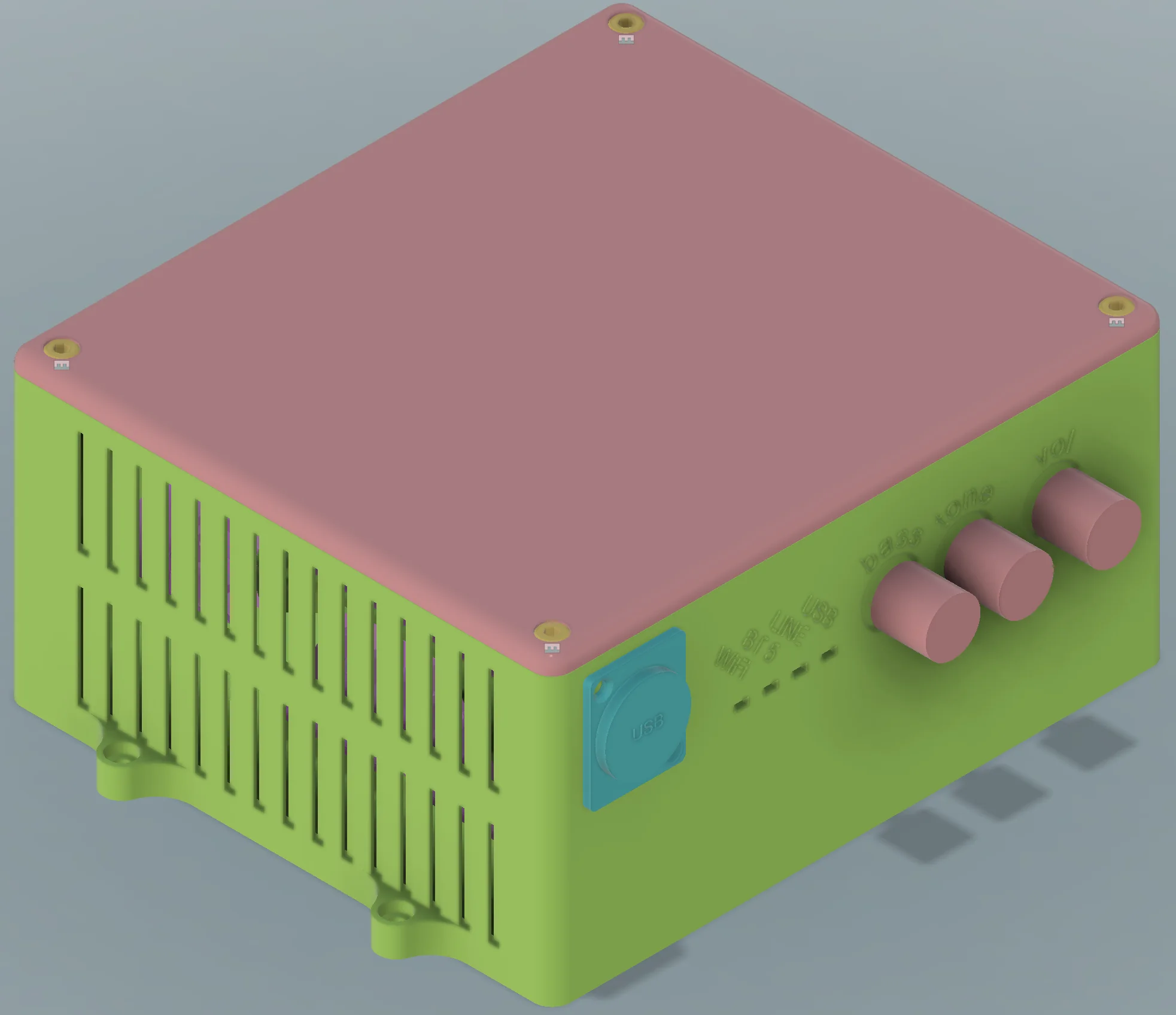
The amp enclosure as seen from the front corner.
The amp enclosure as seen from the rear corner.
Procedure
To give you an idea of how things go together:
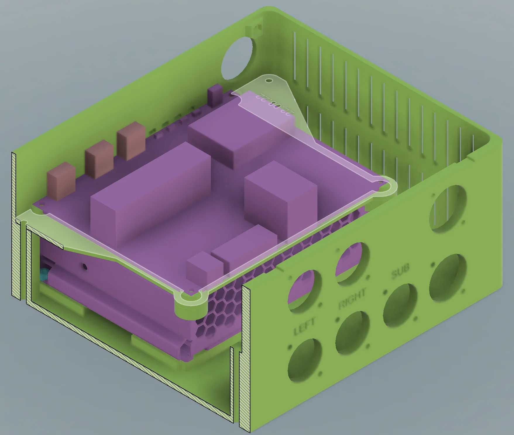
Viewed from the rear corner, the PCB (purple) sits on top of a midplate (green, highlighted) which sits on top of the power supply (also purple, bottom).
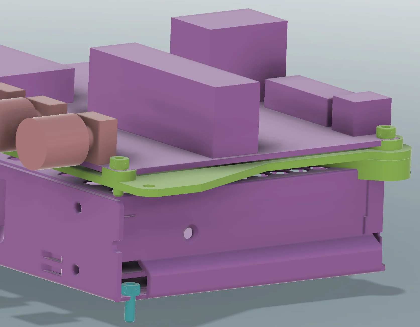
To make printing easier, the midplate is actually two components joined together by the two screws furthest from the knobs.
Just a few things to note:
- The suggested/ideal print orientation should be fairly obvious.
- Tolerances are reasonably tight, you’ll need ~ .15mm tolerance.
- Layer height, material, speed settings are up to you. All that matters is that you can achieve the ~.15mm tolerance.
With respect to the subwoofer skeleton and panels, at least.
Essentially, the more mass in the parts, the more energy will be required to make them rattle/flex/vibrate. The less this happens, the less “extra” noise will be emitted by your subwoofer. Following along with the original instructions for printing, I chose about 35% infill and 3 perimeters for the subwoofer skeleton. Using a .6mm nozzle and some other well tuned slicing settings, I was able to print the entire skeleton in about 40 hours using just over 1 kg of filament. I would plan on at least 80 if using a smaller nozzle with a finer layer height!
Prep screw holes & flashing
In the CAD model, almost all holes meant to receive a screw are intentionally undersized by about .3mm. besides the general ‘it’s easier to expand the hole to the correct size than it is to shrink it’ reason, this is done for one key reason; it eliminates the need for dedicated screw thread hardware.
By intentionally undersigning the hole, you can guarantee there will be a ton of friction generated when inserting the screws for the first time. The excess friction will soften the plastic in the vicinity of the screw threads which allows the plastic to form threads around the screw.
This is not without drawbacks, though so proper procedure is critical for making this work properly!
You must take every precaution to ensure that:
- The screw is driven into the hole in a directly perpendicular direction.
- As the plastic heats up, it becomes easier to knock the screw out of alignment and begin driving it at an angle.
- A constant (slow!) velocity should be used to drive the screw.
- This can be done with hand tools but will result in a pretty tough arm workout! Consider using a power drill with a low speed / constant torque option!
- The threads of the screw will displace some plastic. The excess molten plastic is called flashing and it it almost guarantees that you’ll need to do some post processing / cleanup of the screw holes.
- The molten plastic forms screw threads more or less instantly… but they won’t stay formed until the excess heat has dissipated and the material has solidified.
- Do not remove any screws from the body until they are cool to the touch! This can take several minutes!
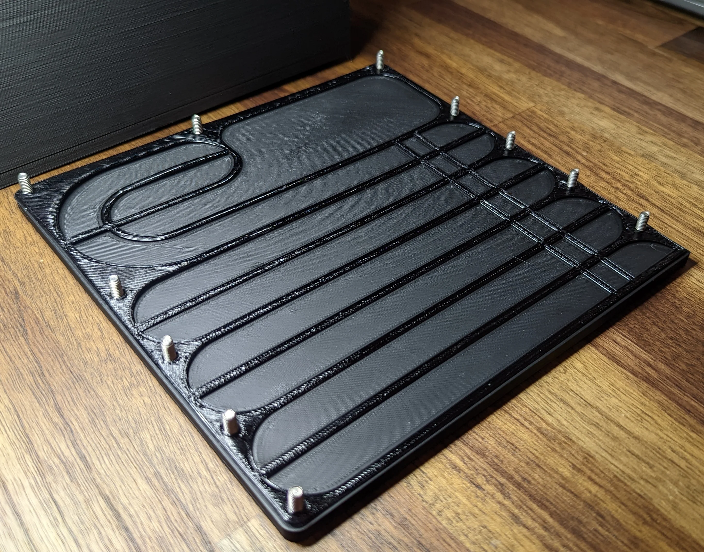
All 11(!) of the m4 screws driven into the sub body waiting for the plastic to set
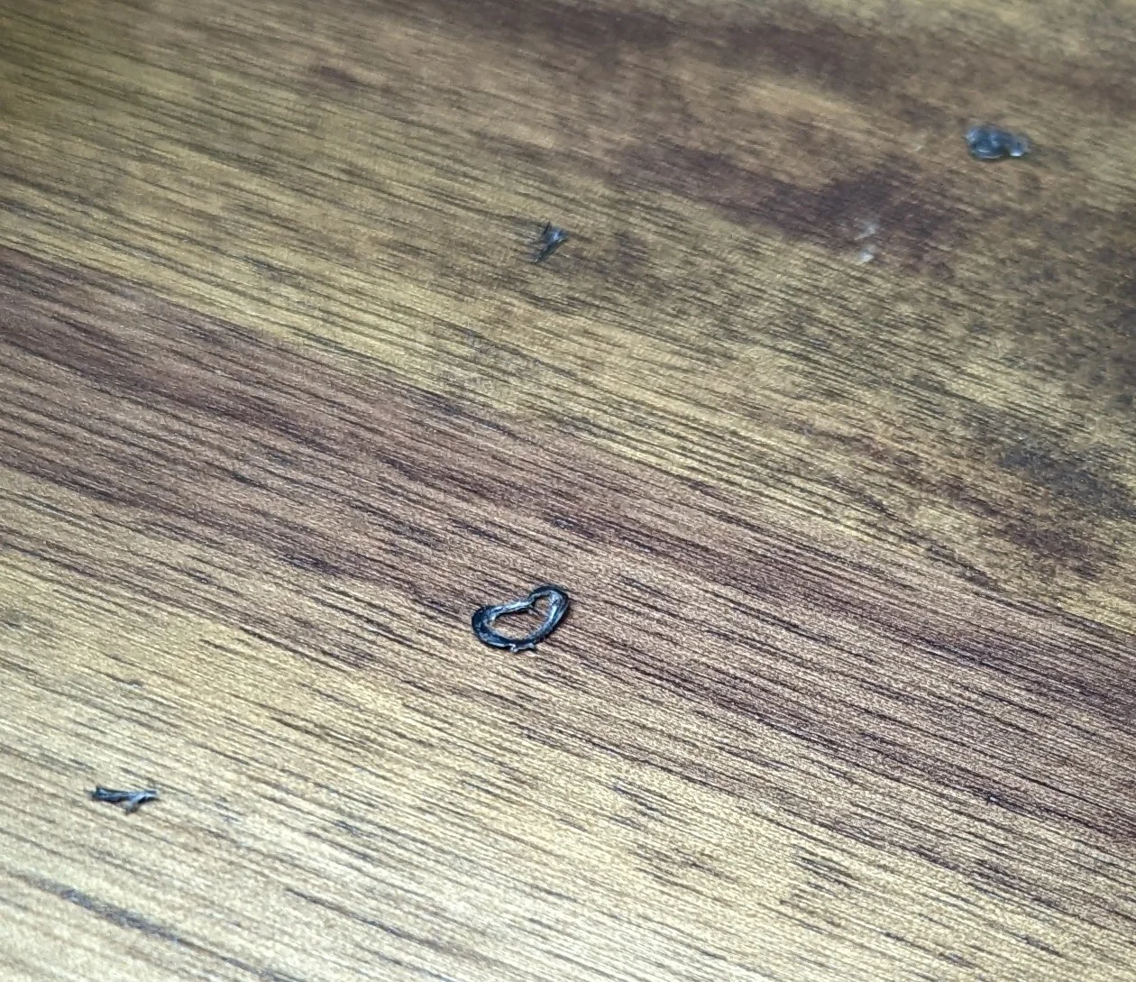
After all 11 screws had cooled and the threads had formed, the screws were removed. Nearly every one of the holes had some (small) build up of material:
Use a straight edge blade or scrape tool to remove the flashing bits.
In some cases, there may be some additional material that builds up on the screw threads themselves. Simply use a different screw for final assembly or use scrape tool or flame to remove the excess material from the threads:
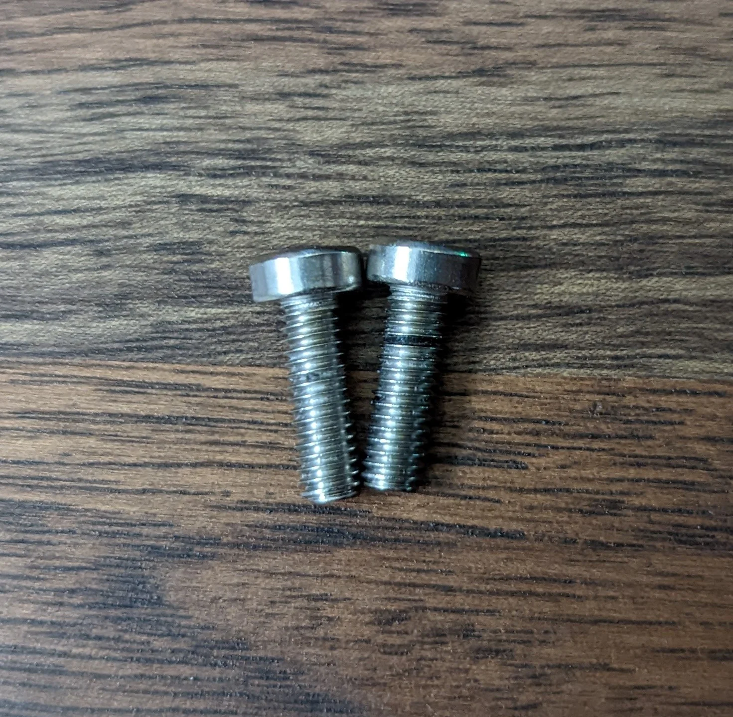
After the flashing is removed from around screw holes you should still be able to see threads within the hole but shouldn’t be able to see/feel any protrusions from the hole:
Where possible, I have made the screw holes much deeper than strictly necessary. As the screw drives deeper, the tip will push molten plastic into this “well”.
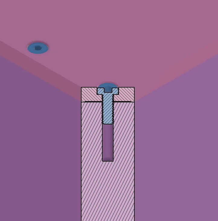
The extra depth on the screw hole gives the molten plastic somewhere to go.
Subwoofer Skeleton
Gaskets
Begin by driving the screws into the side panels and speaker driver then attach the gaskets.
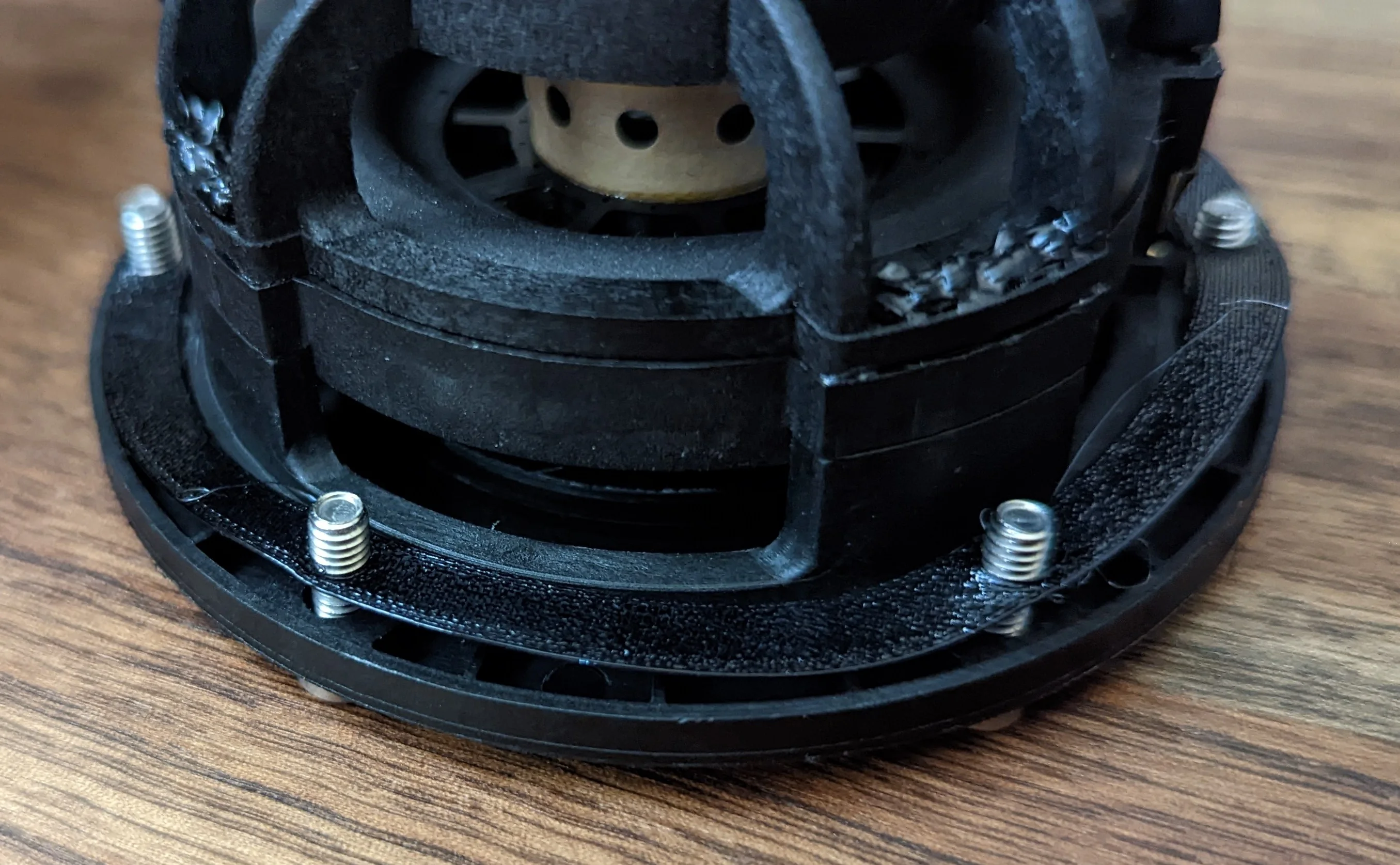

Be mindful of the gasket as you secure the panel to the subwoofer body. Too much torque/clamping force can cause the gasket to distort.
Speaker wire
Solder ~14 inches speaker wire to the RCA jack then install in the housing. Don’t forget to use heat shrink tubing or similar to insulate/protect the electrical connections!
Pass the housing assembly through the speaker hole and the attach the driver and then housing to the back of the subwoofer.
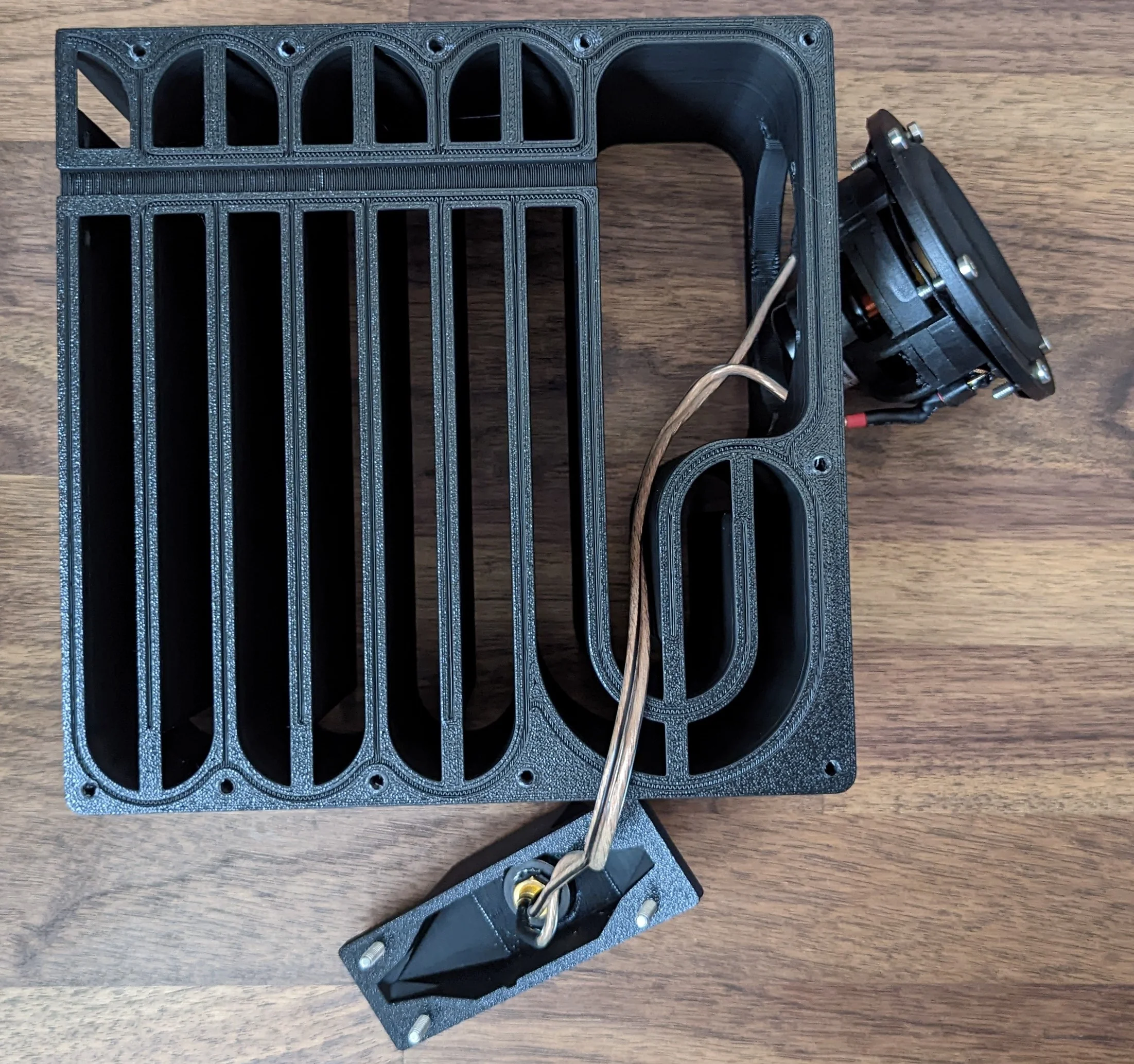
Firmly press the speaker wire into the the cable channel and push any slack wire into the RCA jack housing.
Once the speaker and jack housing are attached to the subwoofer body, simply line up and then attach the panels with the gaskets.
Now is a good time to test that your soldering / connections are working!
If you elected to use the gasket cord material, you would need to spend a non-trivial amount of time carefully cutting and routing segments of the material to fit inside the channel. You will almost certainly want to use superglue or similar to help you hold the material into the channel!
The speaker wire should press-fit into the cable channel more or less sealing it completely.
Amp
Prep
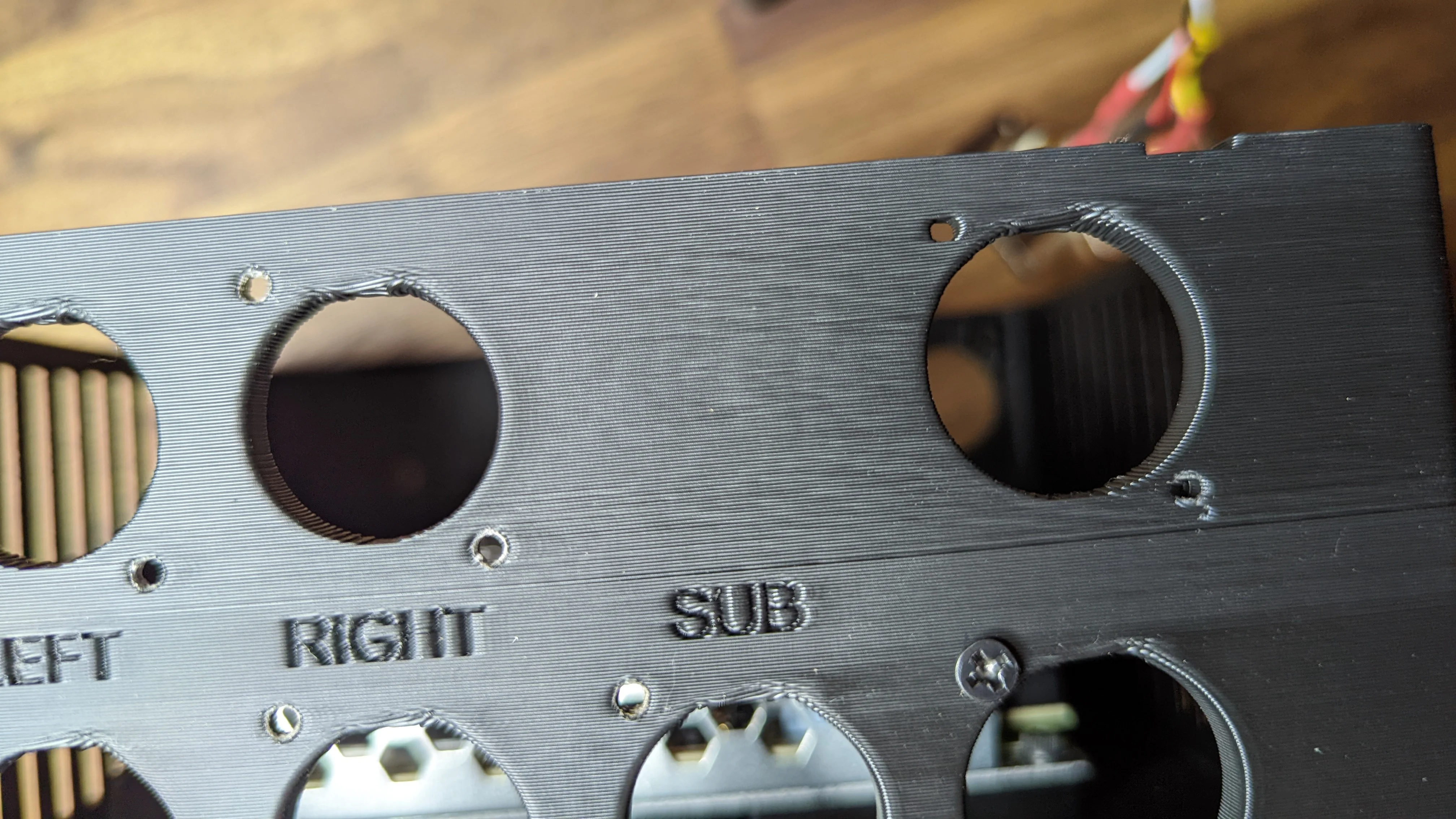
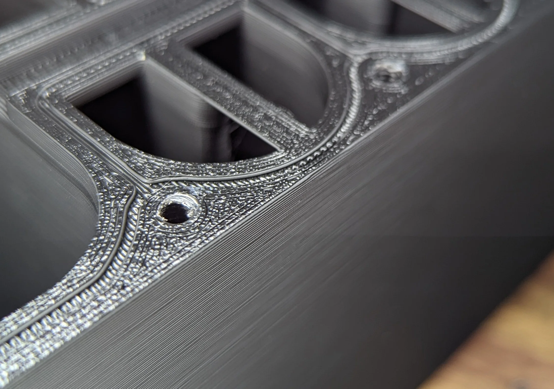
Notice the holes on the left that have been "rightsized" during threading and the holes on the top right that are relatively deformed still.
For the various panel mounted jacks, there are small interior cavities designed to capture the nut. This cavity is actually oversized in the CAD model but due to various printer/slicing factors it is almost certainly going to be a tight fit!
Align the nut with the cavity and then use the screw to pull the nut into the hole then tighten the screw all the way to pull the nuts into place:
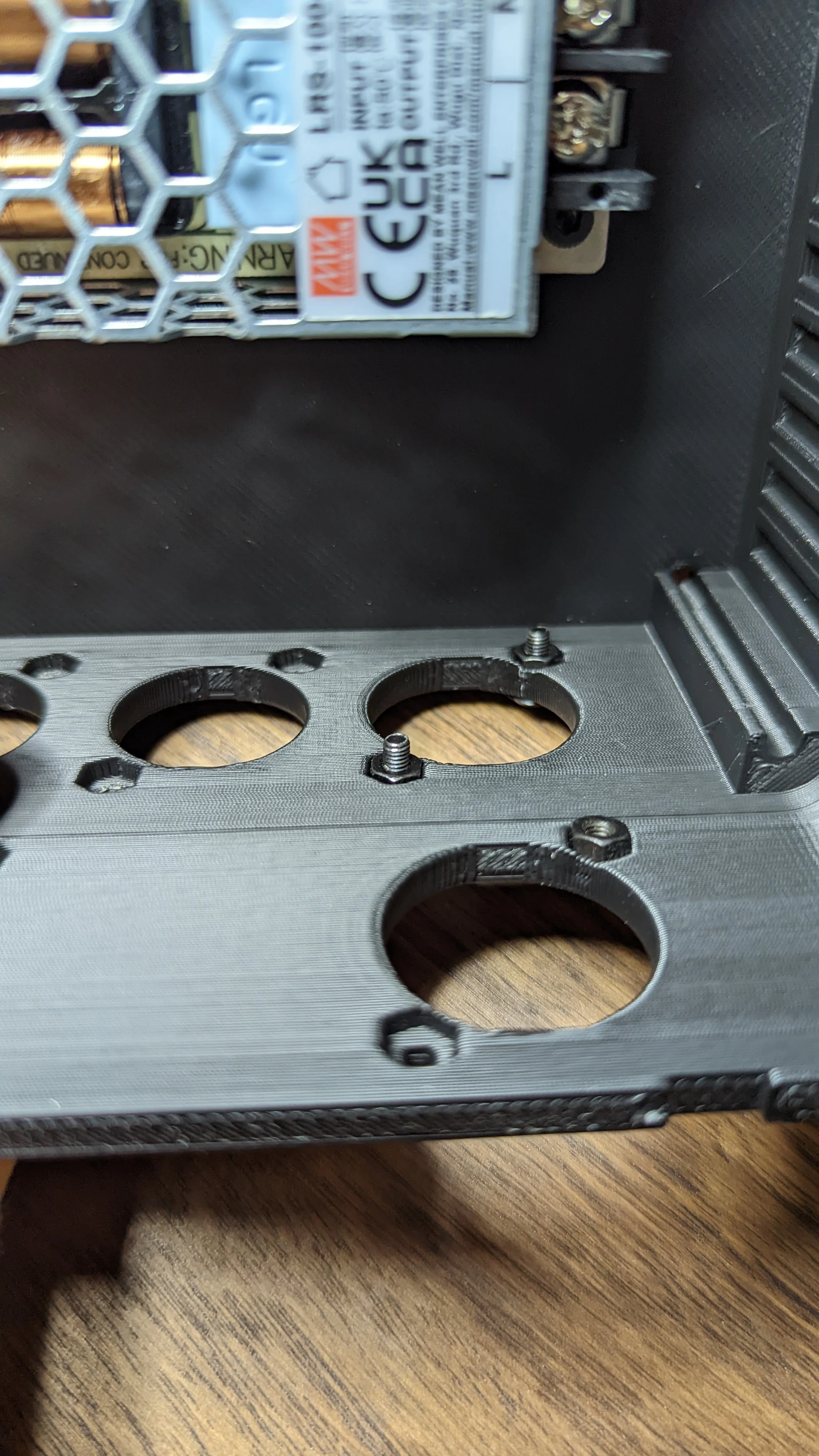
After the screw has pulled the nut into place, it should stay put.
After the various holes have been prepared and the nuts have been fitted, you are ready for final assembly
Assemble
First, combine both parts of the midplate with the amp board. Set aside.
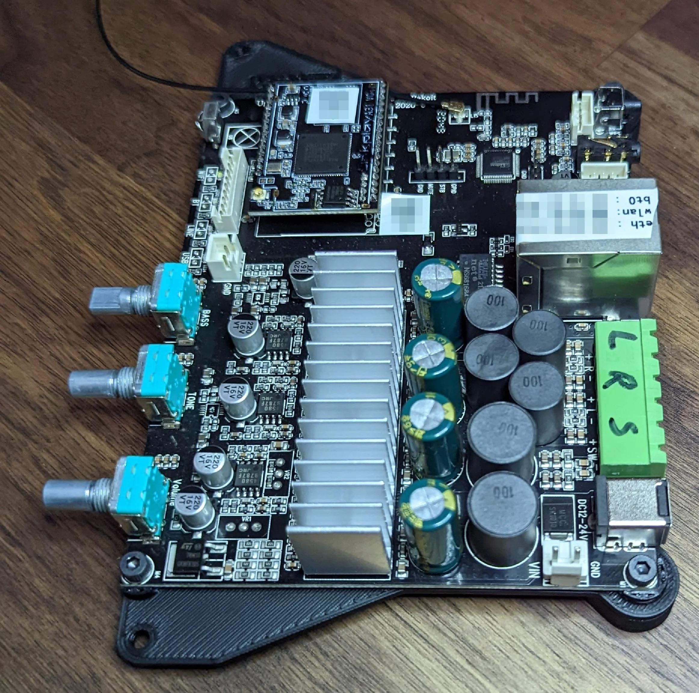
Pro tip: print the MAC addresses of a network device somewhere on the device... Also, don't put unique device IDs onto the internet!
Power
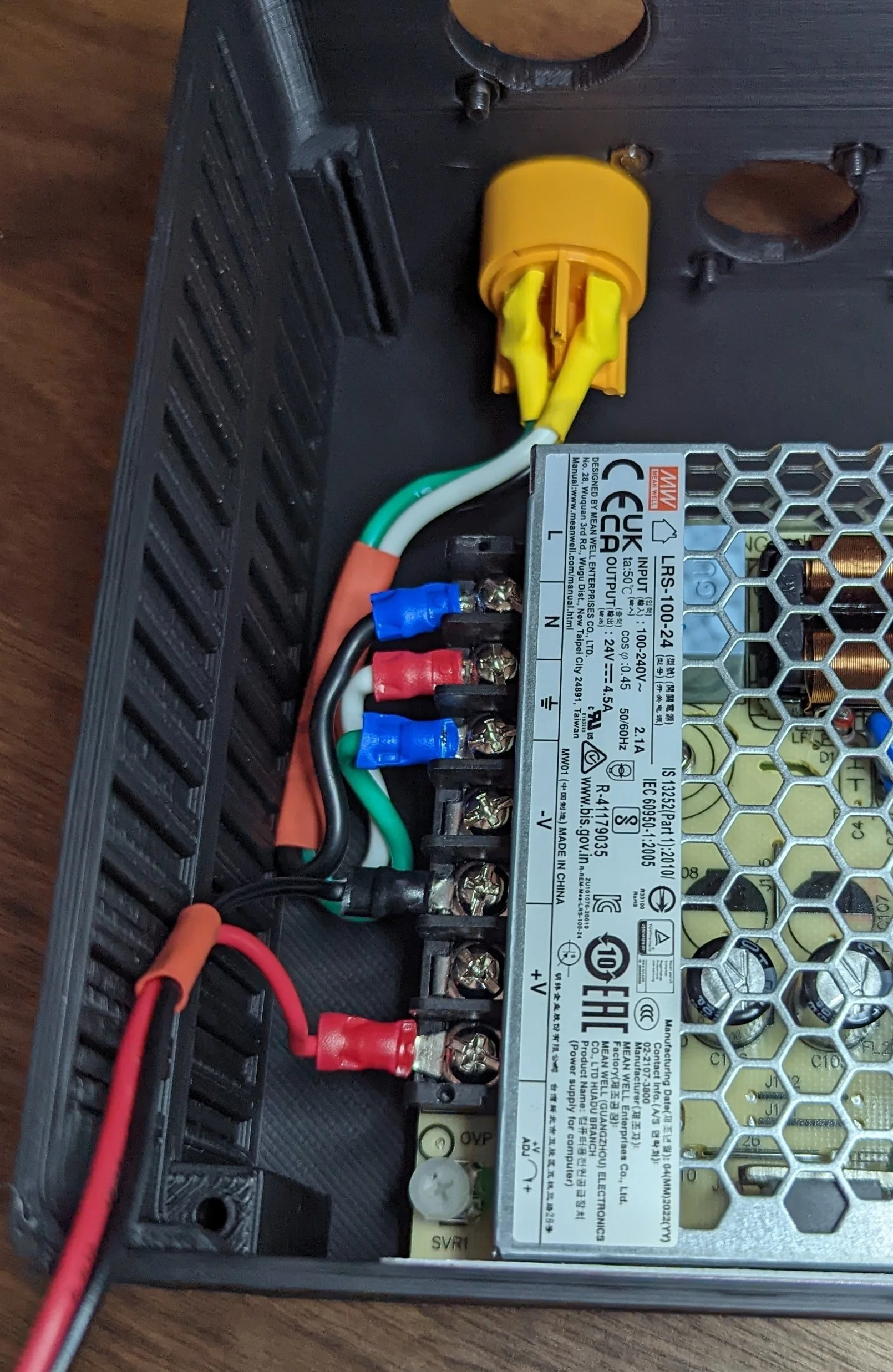
Solder mains wires to the Powercon receptacle and terminate with crimp connectors. Secure the Powercon receptacle to the rear of the enclosure and then attach to the screw terminals on the PSU.
Lower the PSU into the enclosure and secure it with the two screws in opposite corners. Start with the screw closest to the Powercon connector:
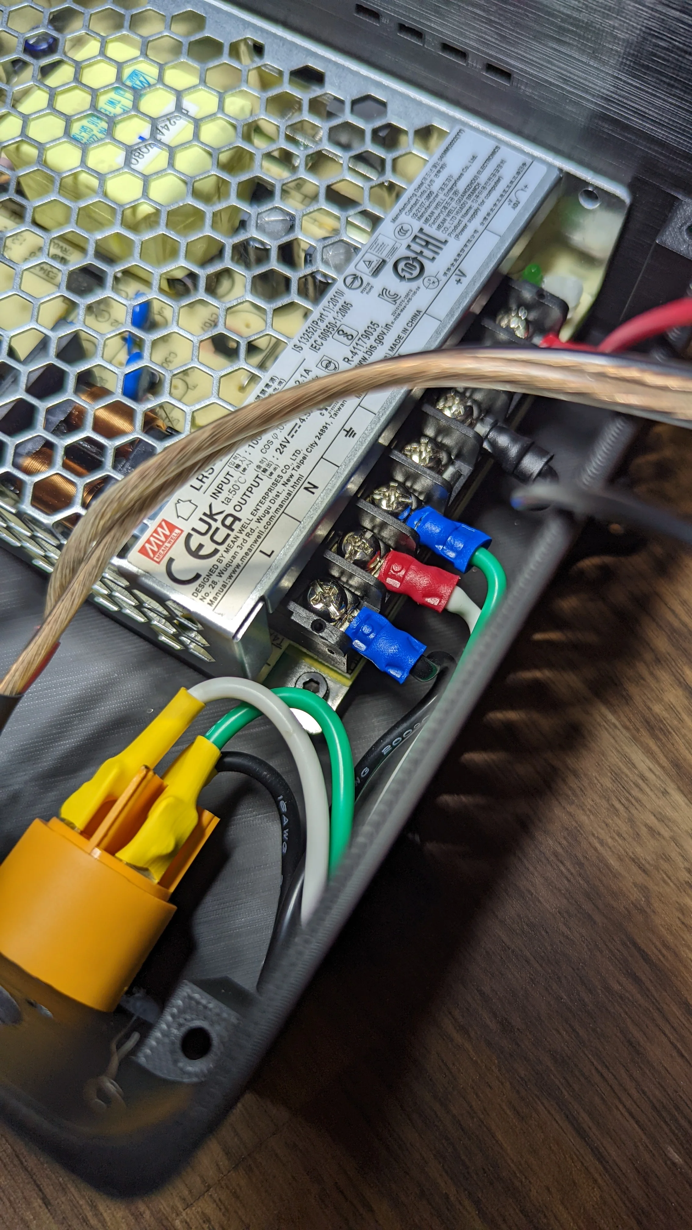
Room inside the enclosure is intentionally tight so do as much wiring/connecting as possible before you start securing things to the enclosure.
Then add the seconds screw in the opposite corner:
Take this opportunity to power up and confirm that the polarity and voltage is correct!
Amp PCB
Push the three rotary encoders through the holes in the enclosure and then lower the midplate/PCB on top of the PSU. Route the DC wires up and around to the DC plug on the PCB.
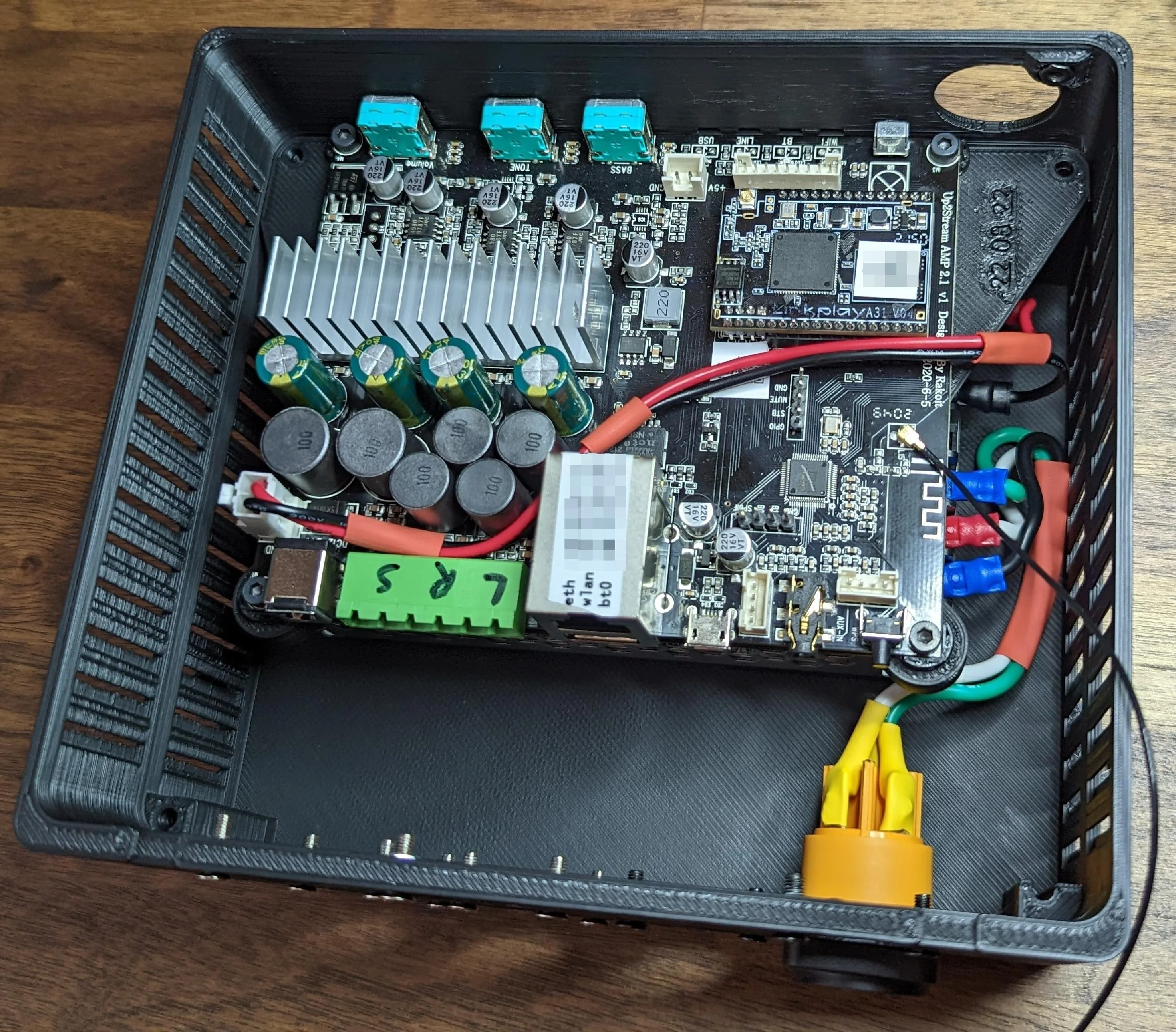
Install the RCA jacks and route wires as needed to the PCB.
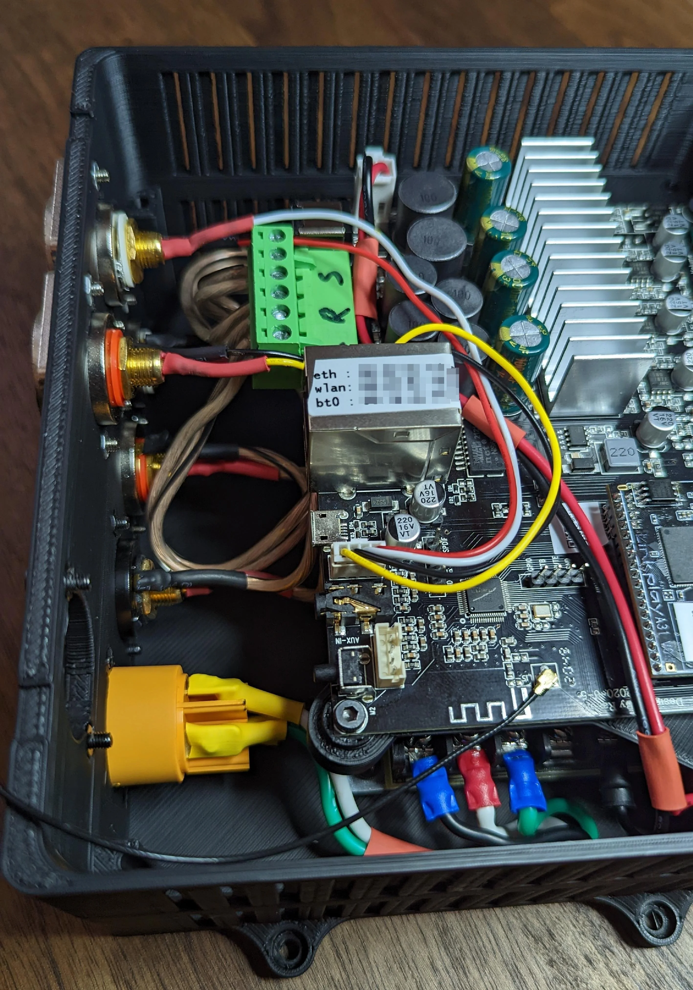
Then connect both the USB and RJ54 jacks on the amp module to their respective panel mount jacks. I forgot to get a picture of the USB cable but it works more or less the exact same way the ethernet cable does:
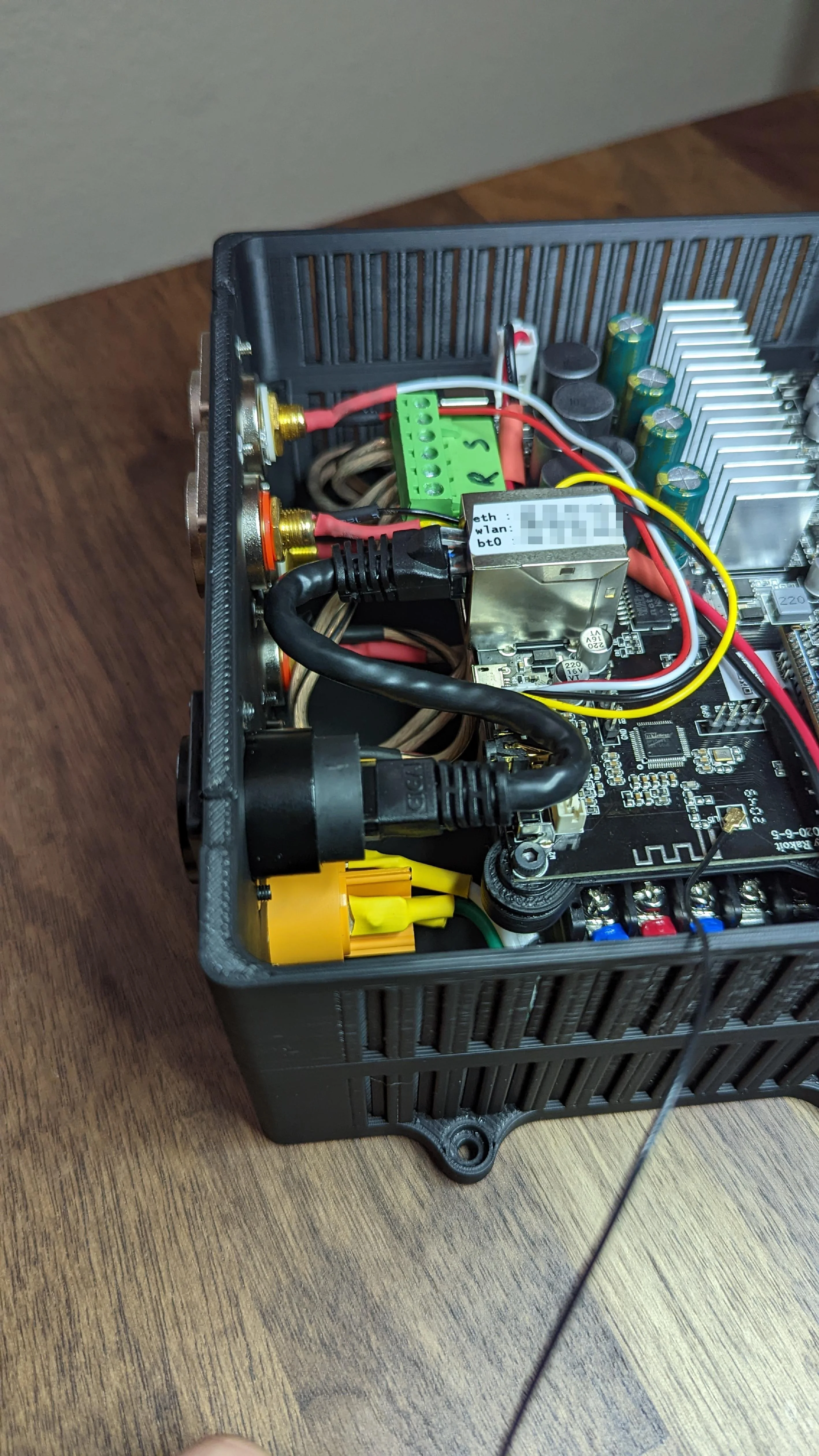
A 6 inch patch cable was quicker but a custom length cable would almost certainly look better. Good thing this will soon be hidden away!
Either remove the BT/WiFi antenna or secure it to the inside of the enclosure just above the LEDs (not pictured here).
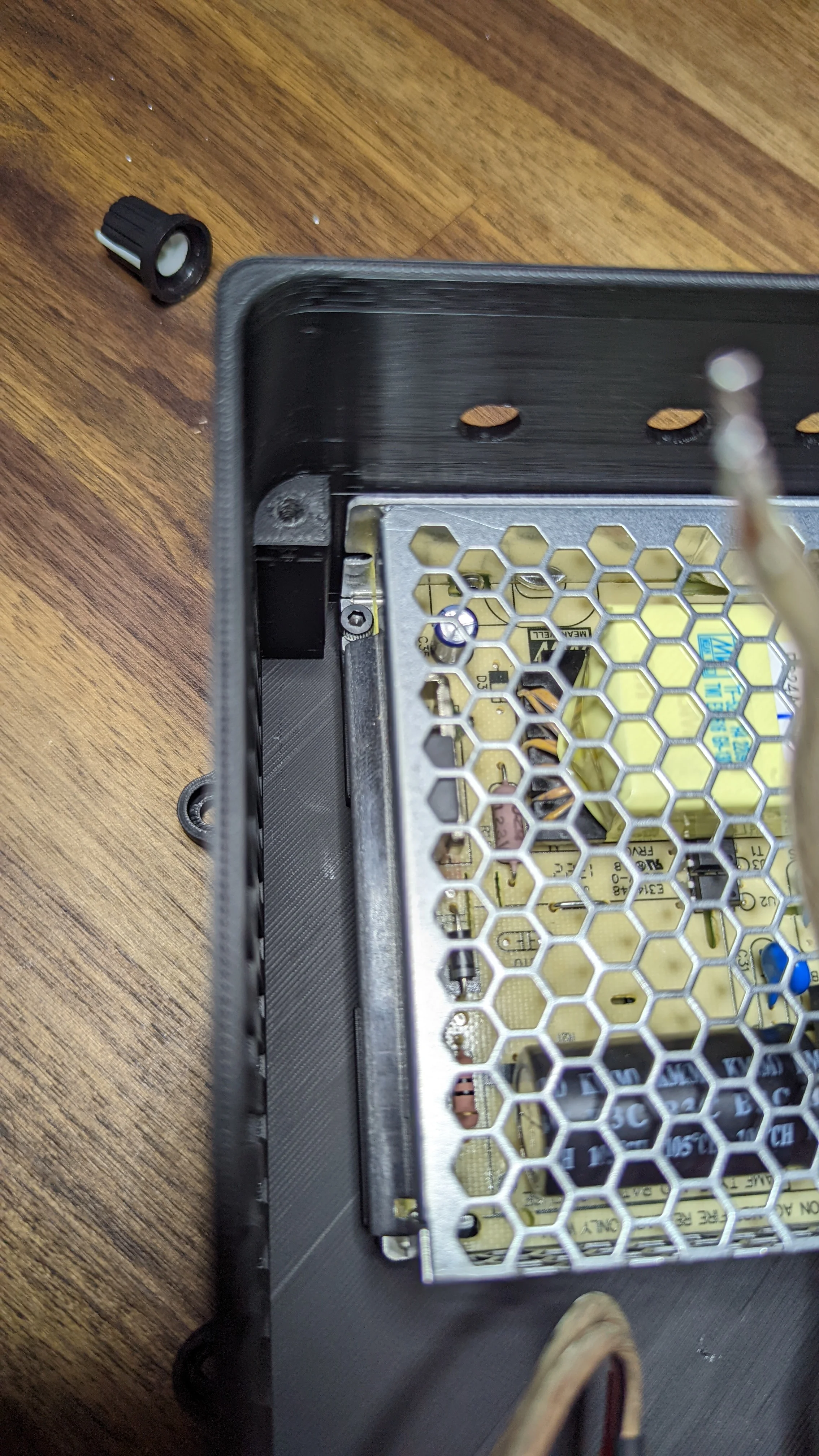
And before attaching the lid, attach the knobs:
Don't forget the washer/nut!
And just like that, the complete sub and amp.
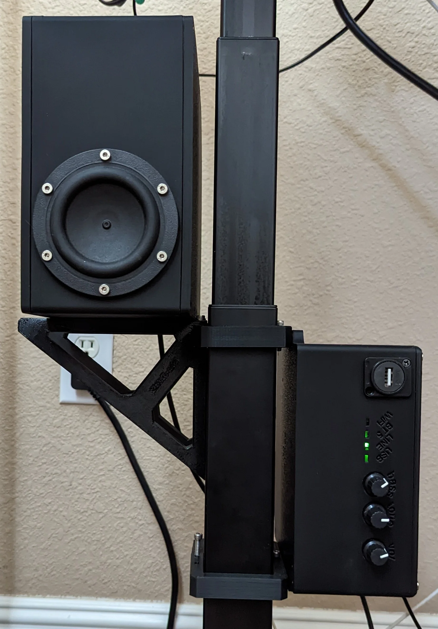
Subwoofer and amp enclosure mounted to the leg of my desk. Please ignore the mess of wires in the background!
Files and licenses
All the 3d printable files associated with this post are available from my printables.com page:
On that page, you will find a list of files like:
❯ tree
.
├── amp-enclosure
│   ├── amp-box-lid.step
│   ├── amp-midplate-1.step
│   ├── amp-midplate-2.step
│   ├── amp-pcb.step
│   └── amp-shell.step
└── sub
    ├── gasket-bottom.step
    ├── gasket-speaker.step
    ├── gasket-top.step
    ├── main-body.step
    ├── panel-bottom.step
    ├── panel-top.step
    ├── rca-enclosure.step
    └── sub-components v28.f3z
All photos used in this post are mine and are licensed under CC BY-NC-SA 4.0.
Everything within the
amp-enclosureis my original work. These files are licensed under CC BY-NC-SA 4.0.Everything in the
subdirectory is based off of the fusion360 file from zx82net which is licensed under CC BY-NC-SA 4.0. Likewise, my modifications fall under the same license.- My modifications in ‘source’ formate are contained in the
sub-components v28.f3zarchive but to make printing easier, individual components are exported as STEP files.
- My modifications in ‘source’ formate are contained in the
Supporting files
In building the various parts in the amp-enclosure directory, I relied on the following additional models: